SERVICING
Ideal Logic Heat - Installation and Servicing
59
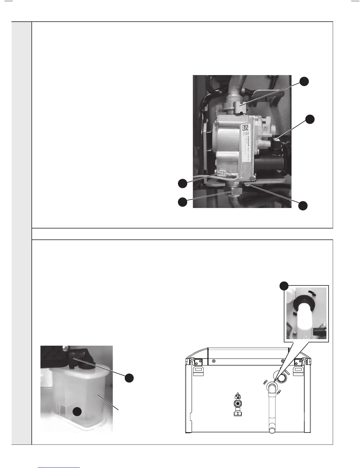
GAS CONTROL VALVE REPLACEMENT
1. Refer to Frame 51.
2.
Unplug the electrical lead connection from the gas
control valve.
3. Disconnect the earth wire.
4. Remove the outlet gas valve clip and slide the
pipe upwards
5. Undo the gas inlet pipe union at the inlet to the
gas valve.
6. Undo the single screw xing the gas valve to
the mounting bracket and withdraw the valve
forwards.
7. Fit the new gas control valve ensuring that the
O ring and sealing washer are in place and
reconnect gas and electrical connections.
8. Check operation of the boiler. Refer to Frames
40 & 41.
1. Refer to Frame 51.
Note: Ensure condensate trap is fully drained before removal.
2. Pull off the rubber pipe at the sump drain.
3. Disconnect the condensate drain pipe.
4. Turn the siphon clockwise to disengage and lift to remove.
5. Reassemble in reverse order.
6. When reassembling ensure the trap is full of water.
7. Check operation of the boiler. Refer to Frames 40 & 41.
60
3
2
Siphon
4
3
5
6
4
2
SERVICING
 Loading...


