37
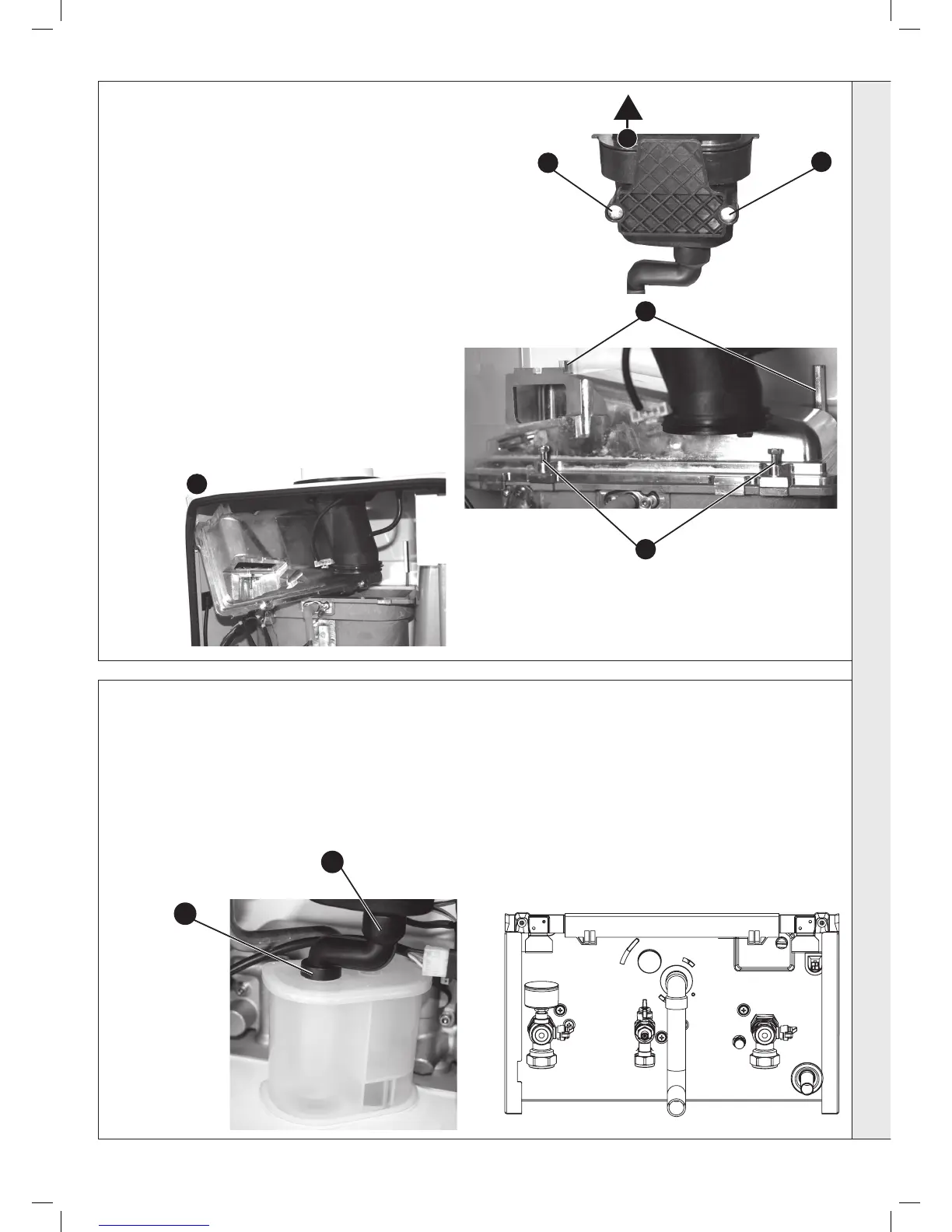
BURNER REMOVAL AND CLEANING
1. Ensure the sump is fully drained
2. Undo the two screws and remove the sump cover retaining the lower
ue manifold.
3. Lift the manifold to clear the bottom sealing gasket and remove
manifold.
4. Remove the 2 burner front xing screws and loosen the 2 rear
extended nuts by at least ten turns.
5. Lift off the burner from the combustion chamber. To facilitate the
removal angle the burner as shown.
IMPORTANT
The burner head is a ceramic plaque construction. Care must be
taken to ensure that the burner is not placed down upon
its face as this may cause damage to the ceramic.
6. Brush off any deposits that may be on the ceramic with a
SOFT brush.
7. Inspect the sealing gasket around the burner for any signs
of damage. Replace as necessary.
1. Pull off the rubber pipe noting the position and ush out any deposits with
clean water.
2. Replace the cleaning plug and rell the siphon with water.
3. Replace the rubber pipe connector with the twin wall seal tted to the
condensate siphon.
38
CLEANING THE CONDENSATE TRAP/SIPHON
1
3
2
2
4
4
5
3
SERVICING