14
11
12
10
60
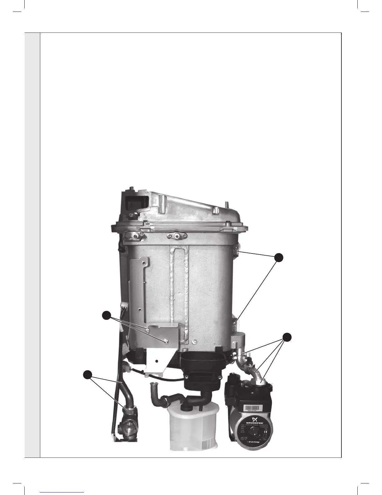
HEAT ENGINE RENEWAL
Refer also to Frame 5 - ‘Boiler Exploded View’
IMPORTANT
Before starting the removal procedure, protect the gas and electrical controls with a waterproof sheet or plastic bag.
12. Undo the ow pipe union nut and remove pipe.
13. Remove the condensate rubber pipe. Refer to Frame 50, no.
2.
14. Remove the two heat exchanger xing screws.
15. Remove the Heat exchanger.
16. Reassemble in reverse order, ensuring the heat exchanger
LH retaining bracket is correctly positioned. Replace any
new ‘o’ rings supplied with new heat exchanger and replacing
gaskets or seals if any sign of damage is evident. When
replacing the spring clips located on both the ow and return
pipe connections, ensure clip is oriented to correctly match
connecting pipe diameters.
17. Ensure the trap/siphon is lled with water. Refer to Frame 50.
18. Rell the boiler. Refer to Frame 23.
19. Check operation of the boiler. Refer to Frames 30 & 31.
1. Refer to Frame 41.
2. Drain the boiler. Refer to Frame 53.
3. Remove the fan / venturi assembly and place on one side.
Refer to Frame 42.
4. Remove the burner and place on one side. Refer to Frame
44.
5. Remove the ignition and detection electrodes. Refer to
Frames 46 & 47.
6. Remove the spark generator. Refer to Frame 48.
7. Remove the gas valve. Refer to Frame 49.
8. Remove the expansion vessel. Refer to Frame 61.
9. Remove the control/no ow thermistor. Refer to Frame 59.
10. Remove the 2 M5 screws retaining the gas valve mounting
bracket and transfer bracket to the new heat exchanger.
11. Undo the inlet pipe union nut and remove the retaining
spring clip and remove pipe.
SERVICING