Note. Fit the earth strap provided with the PCB
to your wrist and a suitable earth on the boiler
chassis.
1. Refer to Frame 41.
2. Remove the main PCB, refer to Frame 51.
3. Unclip the PCB and lift to clear the mounting
posts.
4. Fit the new PCB ensuring the 4 potentiometer
spindles line up with the control knobs which
must be in a vertical position.
5. Reassemble in reverse order.
6. Check operation of the boiler. Refer to Frames
30 & 31.
52
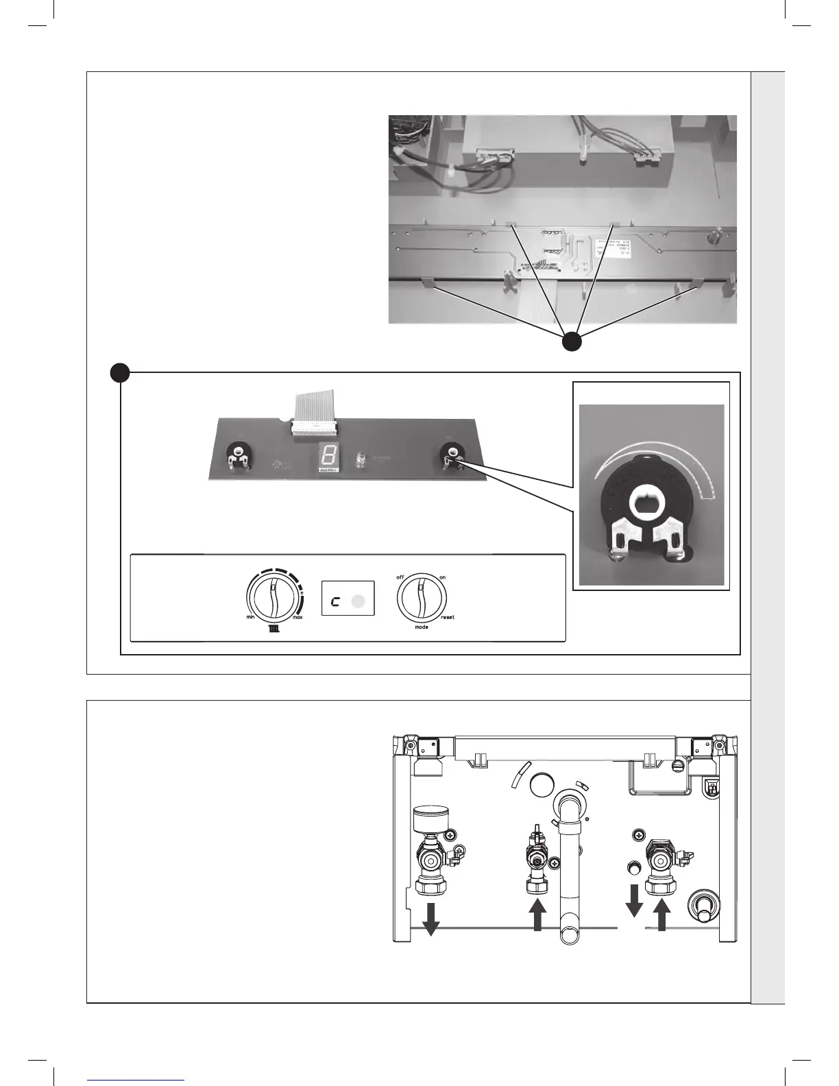
USER CONTROL PCB REPLACEMENT
3
Potentiometer spindle
Control Knobs (to be in vertical position)
PCB
4
53
DRAINING THE BOILER
CENTRAL HEATING CIRCUIT
1. Refer to Frame 41.
2. Close all the CH water isolating valves on the
boiler inlet.
3. To drain the primary heat exchanger circuit:
Open the drain valve and attach a length of hose
to the CH drain point.
4. After replacing any component on the boiler,
remove the hose, close the drain valve and
open all system isolating valves (re-pressurise
as appropriate) before proceeding to check
operation of the boiler.
5. Check operation of the boiler. Refer to Frames
30 & 31.