3
39
CLEANING THE HEAT EXCHANGER
Note: Ensure the condensate trap/siphon
is fully drained before cleaning. Refer to
Frame 50.
1. Remove ignition and ame detection
electrodes. Refer to Frames 46 & 47.
2. It is advisable to replace the sump cover
prior to the water ush process.
3. Thoroughly ush the heat exchanger
by pouring water into the top of the
combustion chamber ensuring the full top
area is covered.
4. Remove the sump cover and clean loose
deposits from the sump.
5. Inspect the ignition and detection
electrodes. Ensure that they are clean
and in good condition - replace if
necessary.
6. Re-t the ignition and ame detection
electrodes, ensuring that both earth tabs
are tted to ignition electrode.
7. Check that the ignition and detection gaps
are correct. Refer to Frames 46 & 47.
1
Ignition Electrode
Flame Detection
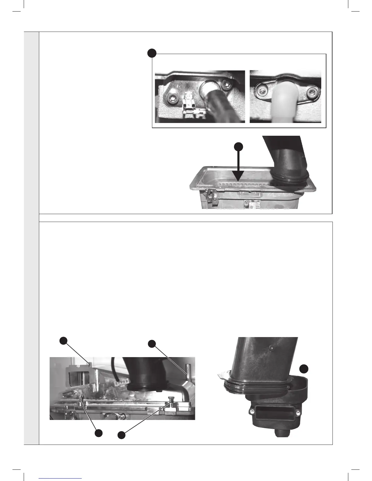
Reassemble the boiler in the following order:
1. Ensure that the condensate trap/siphon is full of water.
2. Ret the burner ensuring the sealing gasket is correctly
positioned and free from damage (tighten the 4 xing screws
in the sequence shown below).
3. Ret the fan / venturi assembly ensuring the retaining tabs
are correctly positioned and the sealing gasket is correctly
positioned and free from damage.
4. Reconnect the fan electrical leads.
5. Remove the sump cover and ret the lower ue manifold as
shown.
6. Ret the sump cover.
40
REASSEMBLY
5
1
7. Ret the boiler front panel.
IMPORTANT. Ensure that the boiler front panel is
correctly tted and that a good seal is made.
8. Swing the control box back into its working position and
secure.
9. Turn on the gas supply at the gas service cock.
10. Reconnect the electrical supply.
11. Check the operation of the boiler. refer to Frames 30 &
31.
2
4
.
3
SERVICING