62
BOILER SEALING PANEL SEAL REPLACEMENT
61
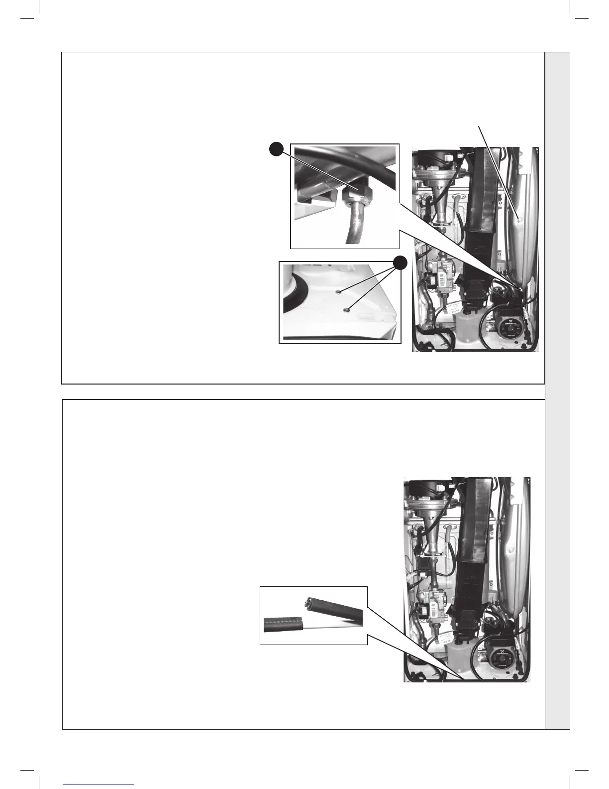
EXPANSION VESSEL RECHARGING & REPLACEMENT
7
8
1. Refer to Frame 41.
2. Remove the old seal from the casing and
thoroughly clean the casing surfaces.
3. Fit the new seal, ensuring the bottom joint
provides an air tight seal.
5. Reassemble in reverse order.
6. Check operation of the boiler. Refer to
Frames 30 & 31.
Note. Ensure that the boiler front panel is
correctly sealed, compressing the seal
to make an airtight joint.
RECHARGING
1. Remove the charge point cover.
2. Recharge the tank pressure to 0.75 bar.
3. Re-assemble in reverse order
4. Check operation of the boiler. Refer to Frames 30
& 31.
REPLACEMENT
5. Refer to Frame 41.
6. Drain the boiler CH circuit. Refer to Frame 53.
7. Unscrew the union nut on the vessel water
connection pipe.
8. Support the expansion vessel and unscrew the 2
screws from the securing clamp, located on the top
of the boiler, and remove. (Note the position of the
bracket on the vessel)
9. Remove the expansion vessel.
10. Fit the new expansion vessel.
11. Reassemble in reverse order.
12. Rell the boiler. Refer to Frame 23.
13. Check operation of the boiler. Refer to Frames 30
& 31.
Recharge
Point
SERVICING