49
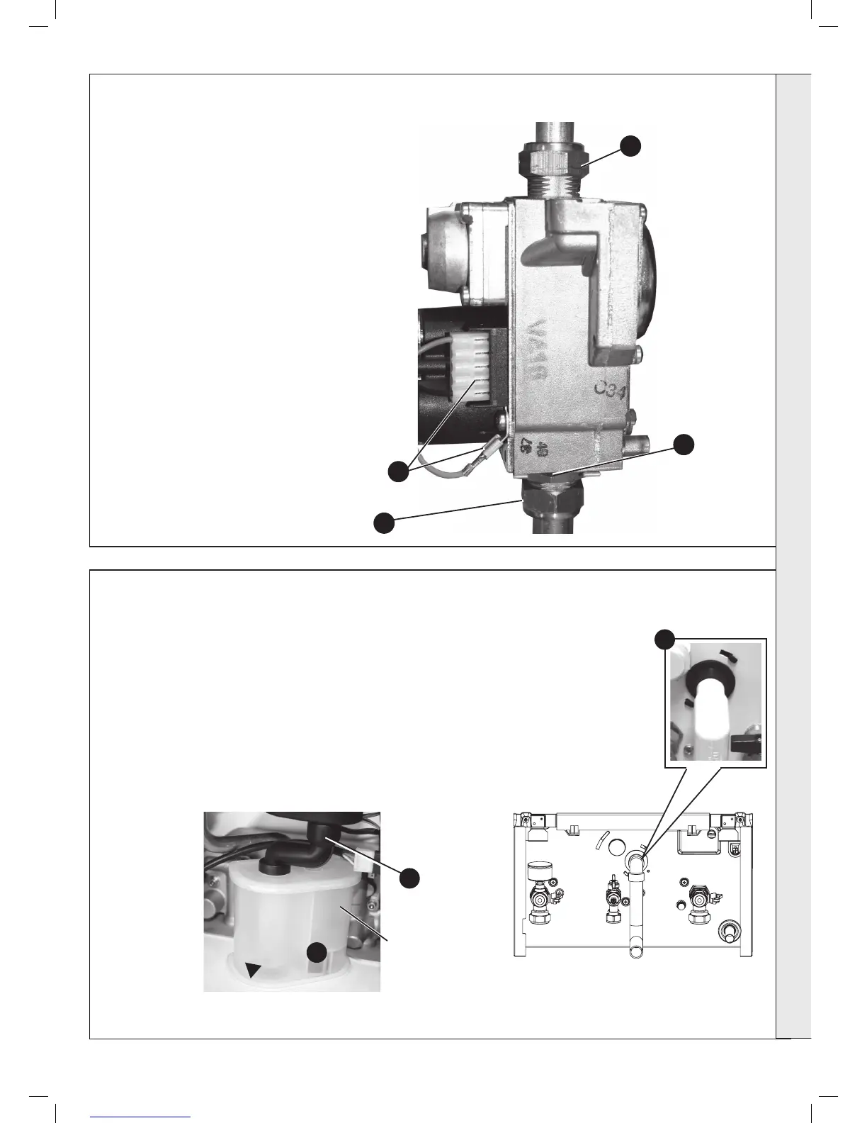
GAS CONTROL VALVE REPLACEMENT
1. Refer to Frame 41.
2. Unplug the electrical lead connection from the
gas control valve and disconnect the earth wire.
3. Undo the union nut on the outlet of the gas
control valve.
4. Undo the gas inlet pipe union at the inlet to the
gas control valve.
5. Loosen the back nut retaining the valve to the
bracket and withdraw the valve forwards.
6. Fit the new gas control valve ensuring the two
sealing washers are in place and reconnect gas
and electrical connections.
7. Check operation of the boiler. Refer to Frames
30 & 31.
2
4
5
3
1. Refer to Frame 41.
Note: Ensure condensate trap is fully drained before removal.
2. Pull off the rubber pipe at the sump drain.
3. Disconnect the condensate drain pipe.
4. Turn the siphon clockwise to disengage and lift to remove.
5. Reassemble in reverse order.
6. When reassembling ensure the trap is full of water.
7. Check operation of the boiler. Refer to Frames 30 & 31.
50
CONDENSATE TRAP/SIPHON REPLACEMENT
3
2
Siphon
4
SERVICING