23
CONNECTIONS & FILLING
NOTES.
Ensure all boss blanking plugs are removed before connecting hardware. Each valve must be tted to the correct boss as shown
in the picture.
Note that all isolation handles are
shown in the open position.
WATER CONNECTIONS CH
1. Connect the CH ow service valve provided in the hardware
pack to the threaded boss connection provided at the lower
rear of the boiler.
2. Connect the CH return valve.
3. For boiler outputs of 18, 24 & 30:
If connecting the boiler to heating loads in excess of
60,000 Btu/h, connecting ow and return heating systems
pipework must be sized in 28mm diameter at the point of
pipe connection to the boiler tails. Use 22mm x 28mm pipe
adaptors as appropriate.
GAS CONNECTION
IMPORTANT. The gas service cock is sealed with a non-metallic
blue bre washer, which must not be overheated when making
capillary connections. Refer to Frame 1 for details of the position of
the gas connection.
For additional gas supply information refer to “Gas Supply” on page 10.
The safety valve connection, located at the bottom right-hand side of the boiler,
comprises a 15mm diameter stub pipe.
The Installer to provide a comprssion joint on the end of the stub pipe. This assists
with pipe removal when servicing.
The discharge pipe should be positioned so that the discharge of water or steam
cannot create a hazard to the occupants of the premises or damage the electrical
components and wiring.
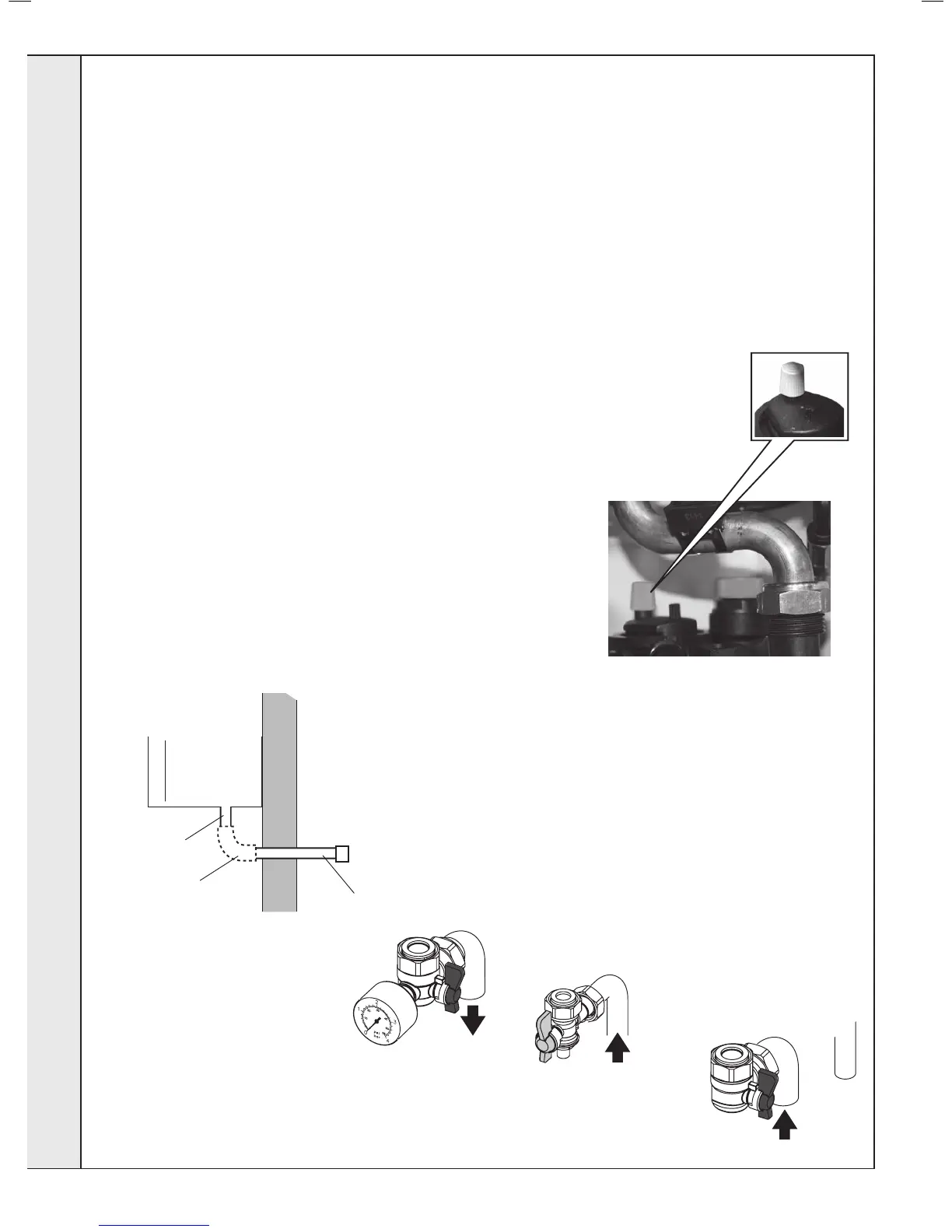
FILLING
IMPORTANT
A. Ensure the dust cap on air vent
located at the rear of the pump
chamber is slightly unscrewed.
B. When lling, there may be a slight
water leak from the air vent therefore
electrical connections should be
protected.
2. Fill and vent the system. Refer
to Frame 2 for lling and setting
pressure procedure.
3. Check for water
soundness.
Dust Cap