58
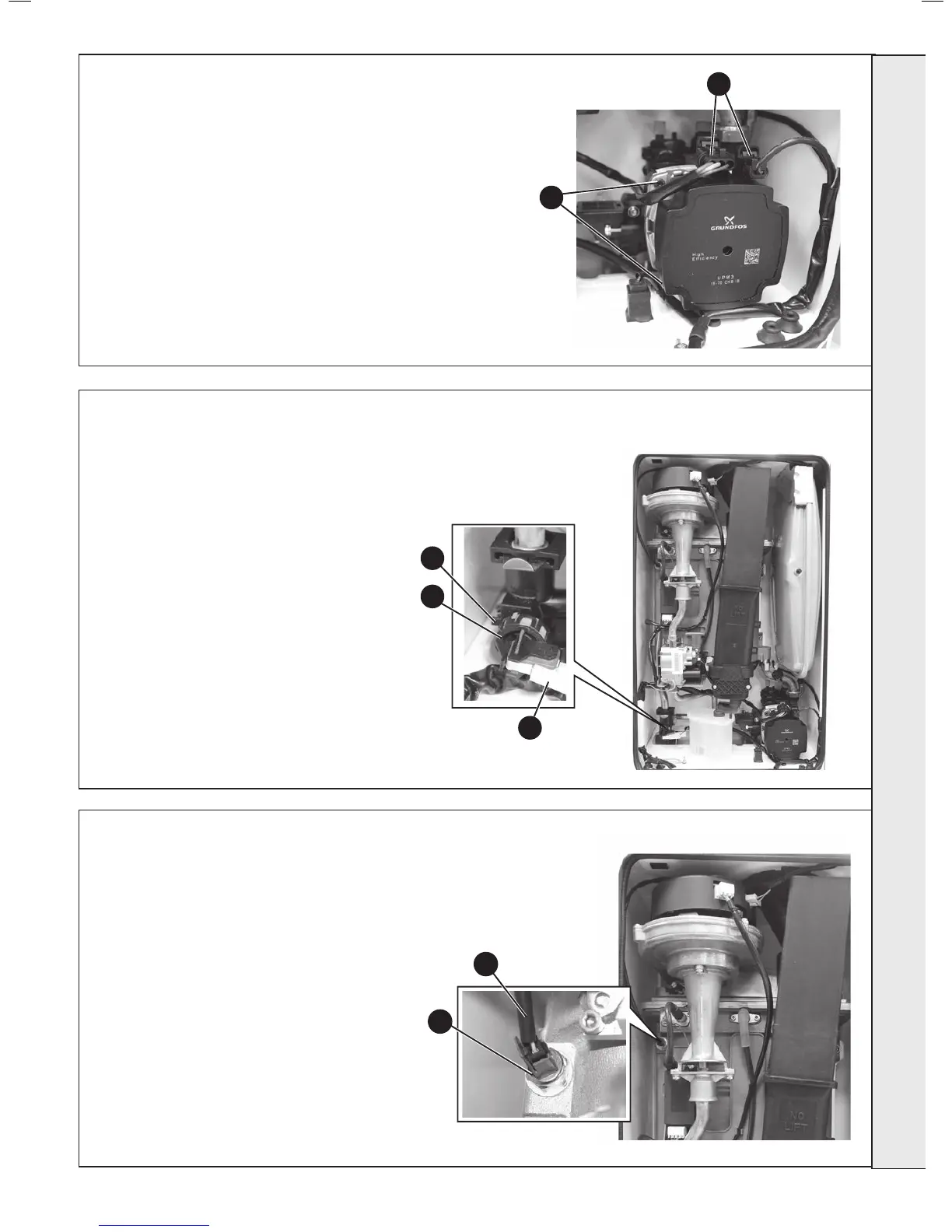
PUMP HEAD REPLACEMENT
1. Refer to Frame 42.
2. Drain the boiler. Refer to Frame 54.
3. Disconnect the two electrical leads from the pump.
4. Remove the 4 Allen screws retaining the pump
head.
5. Remove the pump head.
6. Fit the new pump head.
7. Reassemble in reverse order.
8. Rell the boiler. Refer to Frame 23.
9. Check operation of the boiler. Refer to Frames 31
& 32.
59
CH WATER PRESSURE SWITCH REPLACEMENT
1. Refer to Frame 42.
2. Drain down the boiler. Refer to Frame 54.
3. Unplug the electrical lead.
4. Unscrew the thermistor (to facilitate removal a
13mm socket spanner should be used).
5. Fit the new thermistor using the sealing washer
provided.
6. Reassemble in the reverse order.
7. Rell the boiler. Refer to Frame 23.
8. Check the operation of the boiler. Refer to Frames
31 & 32.
60
4
3
1. Refer to Frame 42.
2. Drain the boiler. Refer to frame 54.
3. Pull off the two electrical connections.
4. Using a suitable tool, pull out the metal
retaining clip.
5. Carefully withdraw the pressure switch.
6. Fit the new pressure switch and re-assemble
in reverse order.
7. Rell the boiler.
8. Check operation of the boiler. Refer to Frames
31 & 32.
3
4
5
3
4