56
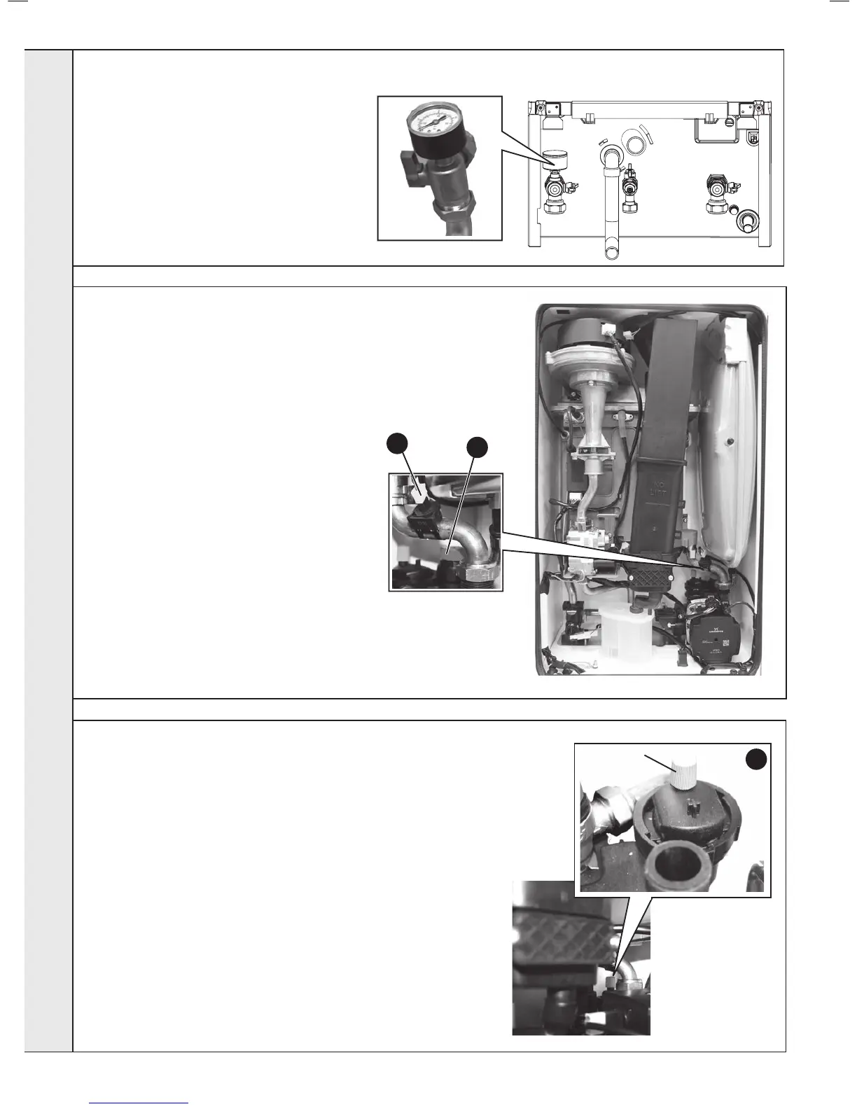
1. Refer to Frame 42.
2. Drain the heating system. Refer to
Frame 54.
3. Unscrew the pressure gauge and
discard.
4. Fit new pressure gauge, using suitable
jointing compound.
5. Rell the boiler. Refer to Frame 23.
6. Check operation of the boiler. Refer to
Frames 31 & 32.
55
PRESSURE GAUGE REPLACEMENT
57
1. Refer to Frame 42.
2. Drain the boiler. Refer to Frame 54.
3. Remove the expansion vessel. Refer to Frame 62.
4. Firstly, increase access area by disconnecting the 22mm pipe connection
at top of pump chamber and bottom of heat exchanger and remove pipe.
5. The automatic air vent head is retained in the pump body with a bayonet
connection. The air vent head and oat assembly is removed by turning
the head anti-clockwise (viewed from above) and pulling upwards.
6. Reassembly is the reverse of the above. Ensure the air vent head ‘o’ ring
seal is in place when retting and the new ‘o’ ring is tted to the return pipe
top connection.
7. Ensure the air vent cap is loose.
8. Rell the boiler. Refer to Frame 23. Check for leaks around the new air
vent joint.
9. Check the operation of the boiler. Refer to Frames 31 & 32.
5
Dust Cap
1. Refer to Frame 42.
2. Drain the boiler. Refer to Frame 54.
3. Remove the clip on return thermistor. Refer
to Frame 46.
4. Pull out and remove the clip (positioned
behind the safety valve) retaining the safety
valve.
5. Undo the safety valve pipe compression
tting positioned outside the boiler casing.
6. Lift out the safety valve/pipe assembly.
7. Remove the safety valve pipe and transfer
to the new safety valve.
8. Reassemble in reverse order ensuring the
retaining clip is correctly tted, the pipe
compression tting retightened and return
thermistor is re-clipped.
9. Rell the boiler. Check operation of the
boiler. Refer to Frames 31 & 32.
3
4