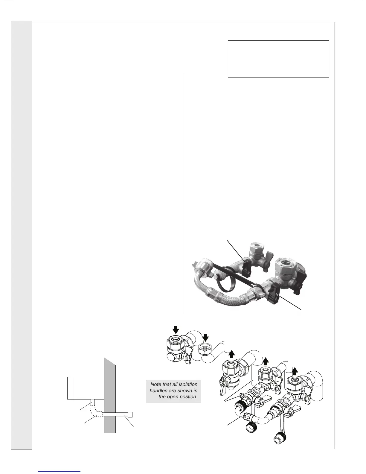
Handle
(Shown in closed position)
Handle
(Shown in closed position)
24
CONNECTIONs & FILLINg
IMpORTANT -whenlling:
When lling, there may be a slight water leak from the air vent
therefore electrical connections should be protected.
Note. The domestic hot water ow rate is
automatically regulated to a maximum:
26 = 10.7 l/m (2.2 gpm)
32 = 13.1 l/m (2.8 gpm)
40 = 16.4 l/m (3.2 gpm)
1. Ensure Filling Loop is connected
2. Ensure dust cap on auto air vent is slackened off .
3. Check all isolation handles on all water connections are in
the open position.
4. Open handle on the lling loop, then slowly open handle
until pressure gauge reads between 1 to 1.5 bar.
5. Once pressure gauge dial reads between 1 - 1.5 bar turn the
lling loop isolation valves back to the closed position.
6. Disconnect lling loop at the LH side, ensuring top hat
washer is retained and screw on blanking cap.
7. Connect extended blanking cap and top hat washer to lling
loop pipe.
FILLINg
Note. Fully open all DHW taps and ensure water is
owing freely. Once satised close all taps.
NOTEs.
Ensure all boss blanking plugs are removed before connecting hardware. Each
valve must be tted to the correct boss as shown in the picture.
Ensure each union is tted with bre seals provided.
Do not subject any of the isolating valves to heat as the seals may be damaged.
WATER CONNECTIONs Ch
1. Connect the CH ow service valve and copper tail
provided in the hardware pack to the threaded boss
connection provided at the lower rear of the boiler.
2. Connect the CH rtn. valve (black handle) and copper tail.
3. If connecting the boiler to heating loads in excess of
17.6kW (60,000 Btu/h), connecting ow and return heating
systems pipework must be sized in 28mm diameter at the
point of pipe connection to the boiler tails. use 22mm x
28mm pipe adaptors as appropriate.
gAs CONNECTION
IMpORTANT. The gas service cock is sealed with a non-metallic
blue bre washer, which must not be overheated when making
capillary connections. Refer to Frame 1 for details of the position
of the gas connection.
For additional gas supply info refer to “Gas Supply” on page 8.
pREssURE RELIEF VALVE DRAIN
The pressure relief valve connection, located at the bottom right-
hand side of the boiler, comprises a 15mm diameter stub pipe.
The Installer to provide a compression joint on the end of the
stub pipe. This assists with pipe removal when servicing.
The discharge pipe should be positioned so that the discharge
of water or steam cannot create a hazard to the occupants of
the premises or damage the electrical components and wiring.
WATER CONNECTIONs DhW
1. Fit the DHW inlet service valve (blue handle) and copper tail
to the threaded boss connection ensuring the seal provided
is correctly located.
2. Fit the DHW outlet pipe tail to DHW outlet connection,
ensuring the seal provided is correctly located.
3. Fit the lling loop provided between the DHW inlet valve an
the CH return valve

 Loading...


