Ideal offer 5 kits as follows:-
(see individual kits for installation instructions)
Combi Mechanical Timer (24 hr): 24 hour mechanical CH timer ts into the control box of the boiler. This can be tted in
conjunction with a Room Thermostat.
Combi Electronic Timer (7 day): 7 day electronic CH timer ts into the control box of the boiler. This can be tted in
conjunction with a room thermostat. Features English language installation help messages.
Combi RF Electro-Mechanical programmable Room Thermostat Kit (24 hr): combined 24 hour mechanical timer and room
thermostat with wireless communication to the receiver unit, which ts into the control box of the boiler.
Combi RF Electro-Mechanical Timer and RF Room Thermostat Kit (24 hr): RF Room Thermostat with wireless
communication to the RF 24 hour electro-mechanical CH timer, which ts into the control box of the boiler.
Weather Compensation Kit: allows outside temperature sensing.
The Vogue Combi boiler comes pre-tted with a link wire between the Room Thermostat/Timer connections on the terminal strip.
This creates a permanent call for heat and must be removed when adding a Room Thermostat/Timer.
27
OpTIONAL sysTEM CONTROLs KITs
28
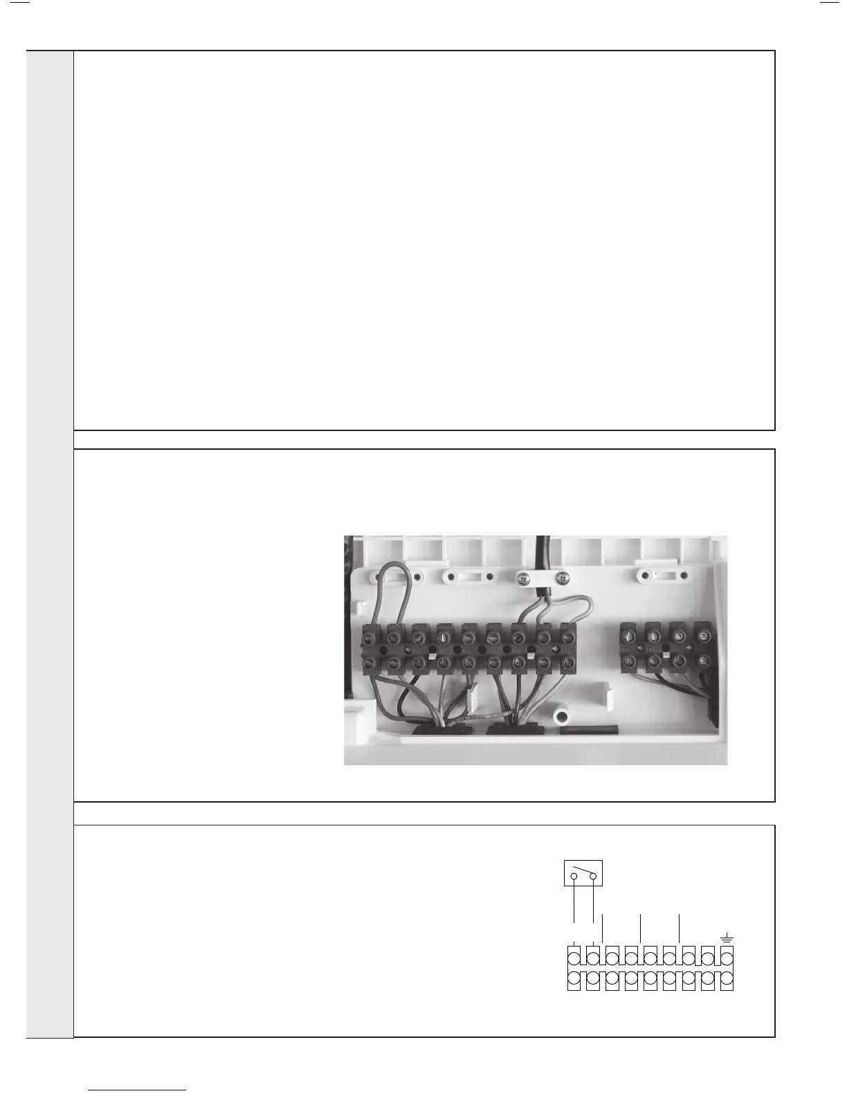
INTERNAL WIRINg
29
INTERNAL WIRINg
To add wired external Room Thermostats,
Timers or Programmers proceed as follows:-
1. Isolate the mains supply to the boiler.
2. Remove the front panel (refer to Frame 9).
3. Swing the control box down into the
servicing position (refer to Frame 46).
4. Route incoming cables through the
grommets in the bottom panel (note:
grommets are ‘blind’ and will require
puncturing) and secure using clamps and
screws provided in the hardware pack.
5. Remove terminal block cover.
6. Connect wires to terminal block.
7. Re-assemble in reverse order.
(A) Internal Timer with Room stat or programmable Room stat
1. Remove the link wire between the Room Stat/Timer terminals
2. Connect the Room Stat or Programmable Room Stat across the terminals as
shown in the Diagram.
3. If the Room Stat has a neutral connection then connect this to the fused spur
neutral.
 Loading...


