30
sysTEM CONTROL WIRINg - CONT’D
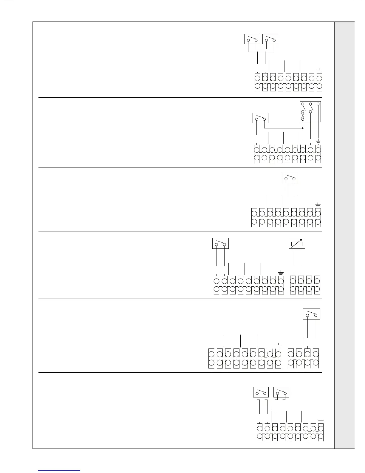
(B) External Timer and Room stat
1. Remove the link wire between the Room Stat/Timer terminals
2. Connect the Room Stat and Timer across the terminals as shown in the
Diagram.
3. If the Room Stat has a neutral connection then connect this to the fused spur
neutral.
(C) Use of general Live for system Controls
1. Remove the link wire between the Room Stat/Timer terminals
2. The live feed to the Room Stat must be isolated by the same isolator that
supplies the boiler.
(D) Frost Thermostat
If parts of the system are vulnerable to freezing or the system controls are likely
to be left off during cold weather then a frost stat should be tted in conjunction
with a pipe thermostat. Position the frost thermostat in the area that is vulnerable
to freezing and then connect it as shown in the diagram. If the boiler is installed
in a garage it may be necessary to t a pipe thermostat, preferably on the return
pipe work.
(E) Weather Compensation
1. Connect the Outside Sensor across the terminals as shown in the
Diagram.
DO nOT COnnECT 230V TO THESE TErMinaLS Or THE BOiLEr
ELECTrOniCS WiLL BE DaMagED
(g) heating zone 2
It is possible to set 2 different ow temperature targets for 2 different
heating zones. To do this Programmable Room Thermostats should be
connected as shown in the Diagram. The Flow Temperature target for
zone 1 is set using the CH temperature Knob, while the Flow Temperature
target for Zone 2 is set using the boiler menu (see Frame 41). Note that
if there is a demand from both zones at the same time then the higher
target temperature will be used.
(F) OpENThERM pROgRAMMABLE ROOM sTAT
1. Remove the link wire between the Room Stat/Timer terminals
2. Connect the OpenTherm Programmable Room Stat across the
terminals as shown in the Diagram.
3. Unclip the 3 way connector from the back of the internal timer plastics
and connect to the 3 way connector adjacent to the plastics.
DO nOT COnnECT 230V TO THESE TErMinaLS Or THE BOiLEr
ELECTrOniCS WiLL BE DaMagED
If parts of the system are vulnerable to freezing or the system
controls are likely to be left off during cold weather then a frost
stat should be fitted in conjunction with a pipe thermostat.
Position the frost thermostat in the area that is vulnerable to
freezing and then connect it as shown in the diagram. If the
boiler is installed in a garage it may be necessary to fit a pipe
thermostat, preferably on the return pipe work.
It is possible to set 2 different flow temperature targets for 2
different heating zones. To do this Programmable Room
Thermostats should be connected
as shown in the Diagram.
The Flow Temperature target for zone 1 is set using the CH
temperature Knob, while the Flow Temperature target for Zone
2 is set using the boiler menu (see Frame XX). Note that if
there is a demand from both zones at the same ti
me then the
higher target temperature will be used.

 Loading...


