67
DRAININg ThE BOILER
CENTRAL hEATINg CIRCUIT
1. Close all the CH water isolating valves on the boiler inlet.
2.
To drain the primary heat exchanger circuit: Open the drain point by
unscrewing using a at blade screw driver and attach a length of drain hose.
3. After replacing any component on the boiler, remove the hose, close
the drain valve and open all system isolating valves (re-pressurise as
appropriate by re-connecting the lling loop, refer to Frame 24) before
proceeding to check operation of the boiler.
4. Disconnect lling loop. Refer to Frame 24.
5. Check operation of the boiler. Refer to Frames 33-36.
DOMEsTIC hOT WATER CIRCUIT
1. Close the DHW water isolating valve on the DHW inlet.
2. To drain the domestic hot water circuit: As there is no direct drain for the
domestic hot water circuit, depending on the location of the boiler, opening
the lowest hot water tap may drain this circuit. However it must be noted that some residual water will be experienced during
replacement of components.
3. After replacing any component on the boiler open the DHW inlet isolating valve and vent the DHW system by opening all hot
taps and ensuring water ows from each tap.
4. Disconnect lling loop. Refer to Frame 24.
5. Check operation of the boiler. Refer to Frames 33-36.
1. Refer to Frames 45 & 46.
2. Refer to Frame 53.
3. Set both the user temperature
selector knobs to the 12 o’clock
position.
4. Remove the electrical cover at the
clips indicated. Refer to Frame
64.
5. Disconnect all electrical
connectors carefully
6. Remove pcb from mounting posts.
7. Replace the pcb in reverse order.
8. Check the operation of the boiler.
Refer to Frames 33-36.
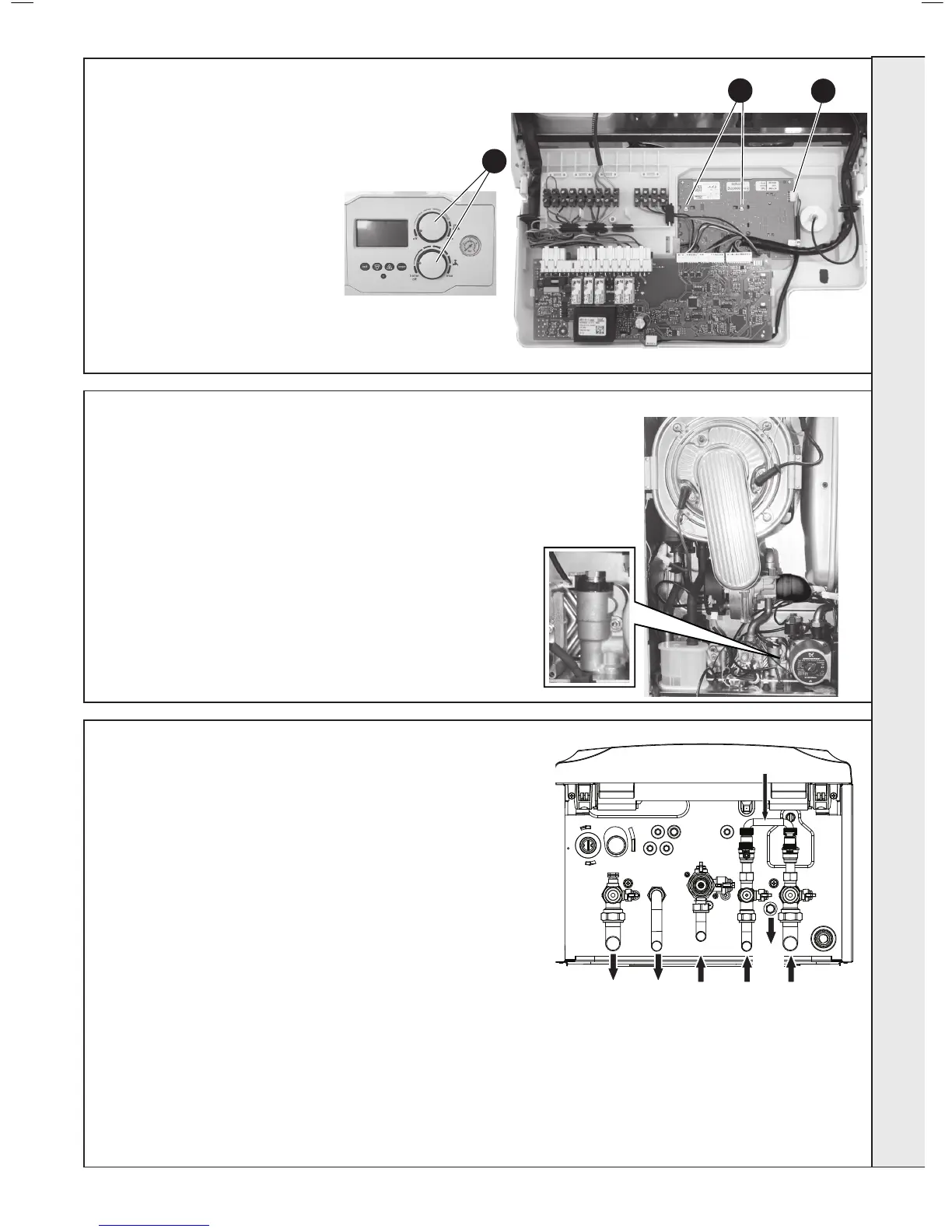
65
UsER pCB REpLACEMENT
3
6
5
66
DhW FLOW TURBINE sENsOR REpLACEMENT
1. Refer to Frames 45 & 46.
2. Refer to Frame 53.
3. Lift off the ow turbine sensor plastic
retaining clip.
4. Unplug the electrical connection and
transfer to new turbine sensor.
5. Reassemble in reverse order.
6. Check operation of the boiler. Refer to
Frames 33-36.
Filling Loop
CH
Flow
DHW
Outlet
Gas DHW
Inlet
CH
Return
CH
Drain
Circuit
sERVICINg
 Loading...


