18: P
ULSE
O
UTPUT
I
NSTRUCTIONS
18-18 FC6A S
ERIES
MICROS
MART
L
ADDER
P
ROGRAMMING
M
ANUAL
FC9Y-B1726
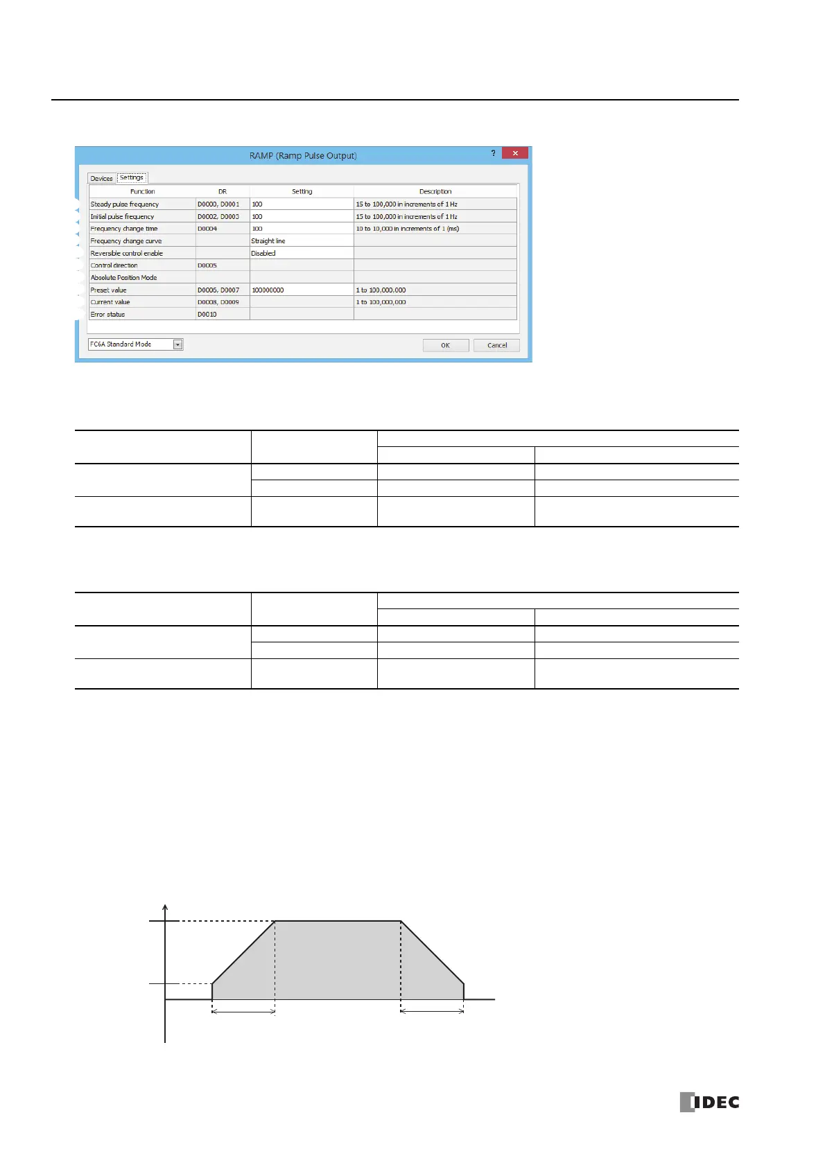
■ Settings tab
6. Steady pulse frequency
This setting specifies the steady pulse frequency after the pulse frequency increases. The output frequency error is ±5%.
The corresponding instruction and frequency differ by the CPU module type.
7. Initial pulse frequency
This setting specifies the frequency when pulse output starts. The output frequency error is ±5%.
The corresponding instruction and frequency differ by the CPU module type.
8. Frequency change time
This setting specifies the time to increase and decrease the pulse frequency.
Set the time between 10 and 10,000 ms in increments of 1 ms. The first digit of the setting is handled as zero. For example, if
144 is entered, the set value is handled as 140 ms.
9. Frequency change curve
The frequency change curve can be selected from Straight line and S-shaped curve.
If S-shaped curve is selected, the initial frequency can be lower, which can suppress vibration and shocks more than Straight
line.
This setting is supported by only the Plus CPU module transistor output type.
Straight line
CPU Module Type Instruction
Configurable Range
Setting Value Frequency
All-in-One CPU Module
RAMP1, RAMP2 15 to 100,000 15 Hz to 100 kHz (increments of 1 Hz)
RAMP3, RAMP4 15 to 50,000 15 Hz to 5 kHz (increments of 1 Hz)
CAN J1939 All-in-One CPU
Module/Plus CPU Module
RAMP1 to RAMP4 15 to 100,000 15 Hz to 100 kHz (increments of 1 Hz)
6.
7.
8.
9.
10
.
11
.
12
.
13
.
14
.
15
.
Steady pulse
frequency
Frequency
Initial pulse
frequency
Total number of pulses
Frequency increase time
Frequency decrease time
 Loading...
