FC6A S
ERIES
MICROS
MART
L
ADDER
P
ROGRAMMING
M
ANUAL
FC9Y-B1726 18-19
18: P
ULSE
O
UTPUT
I
NSTRUCTIONS
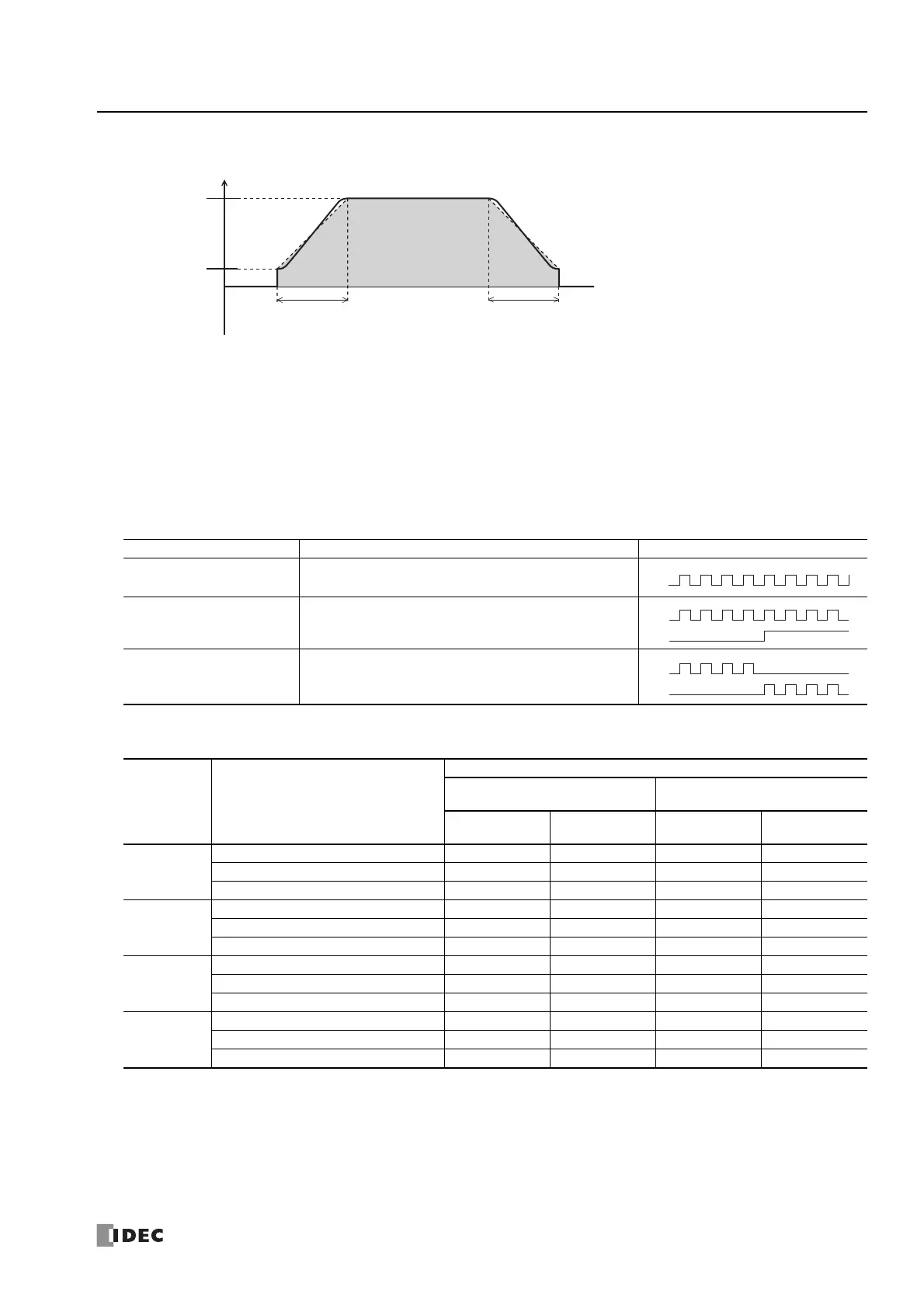
S-shaped curve
Notes:
• The S-shaped curve frequency change curve is approximated with a 3D function based on a setting value. The setting value of the
approximation equation cannot be changed.
• The S-shaped curve frequency change curve changes to a linear curve in the following situations.
• When the frequency change time is less than 100 ms
• When the initial pulse frequency is less than 100 Hz
10. Reversible control enable
This setting enables or disables reversible control and selects the reversible control method from the following reversible control
modes. There are two modes for the pulse output mode: single-pulse and dual-pulse. They can be combined with reversible
control as follows. (This is an example when RAMP1 is used with the All-in-One CPU module.)
The outputs used on the FC6A Series MICROSmart vary based on the instruction used, the combination of the pulse output
mode and reversible control, and the model used.
*1 When using single-pulse output mode with the All-in-One CPU module, Q2 or Q3 will be used, so an instruction that uses the same output
cannot be used.
*2
When using dual-pulse output mode with the All-in-One CPU module, Q1 will be used, so an instruction that uses the same output cannot be used.
11. Control direction
When reversible control is enabled, store 0 in this data register for forward operation and store 1 in this data register for reverse operation.
This is ignored when specify absolute position mode is
Enabled
. If the absolute position counter value subtracted from the target position is
positive,
Forward
is automatically selected, and pulses are output. If negative,
Reverse
is automatically selected, and pulses are output.
Reversible Control Enable Operation Pattern
Reversible control disabled
Select this option when using pulse output in a single
direction. Pulse A and pulse B can be used independently.
Reversible control
Single-pulse output
Pulse A is used as pulse output. Pulse B on/off is used as
reversible control.
Reversible control
Dual-pulse output
Pulse A is used as forward pulse (CW) output.
Pulse B is used as reverse pulse (CCW) output.
Instruction Operating Condition
Output Used
All-in-One CPU Module
CAN J1939 All-in-One CPU
Module/Plus CPU Module
Pulse Output
Reversible
Control Output
Pulse Output
Reversible
Control Output
RAMP1
Reversible control disabled Q0 — Q0 —
Reversible control (single-pulse output) Q0 Q2
*1
Q0 Q1
Reversible control (dual-pulse output) Q0, Q1
*2
—Q0, Q1—
RAMP2
Reversible control disabled Q1 — Q2 —
Reversible control (single-pulse output) Q1 Q3
*1
Q2 Q3
Reversible control (dual-pulse output) — — Q2, Q3 —
RAMP3
Reversible control disabled Q2 — Q4 —
Reversible control (single-pulse output) — — Q4 Q5
Reversible control (dual-pulse output) — — Q4, Q5 —
RAMP4
Reversible control disabled Q3 — Q6 —
Reversible control (single-pulse output) — — Q6 Q7
Reversible control (dual-pulse output) — — Q6, Q7 —
Steady pulse
frequency
Frequency
Initial pulse
frequency
Total number of pulses
Frequency increase time
Frequency decrease time
 Loading...
