19: PID C
ONTROL
I
NSTRUCTION
19-36 FC6A S
ERIES
MICROS
MART
L
ADDER
P
ROGRAMMING
M
ANUAL
FC9Y-B1726
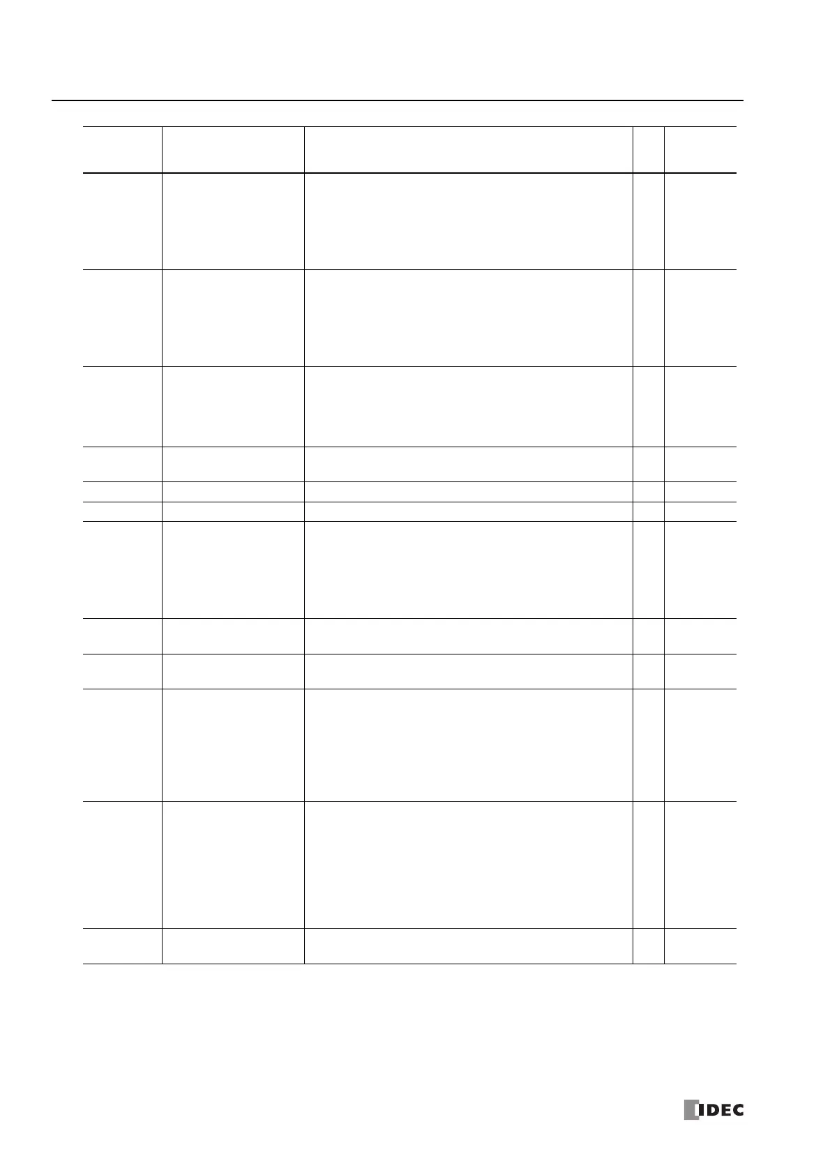
S1+30, S1+31 MV Low Limit
Set MV Low Limit between 0.0 and 100.0 (0.0 and 100.0%).
If the value of MV Low Limit is less than 0.0 or greater than 100.0, the
instruction operates with 0.0. If MV High Limit ≤ MV Low Limit, the
instruction operates with MV Low Limit as 0.0 and MV High Limit as
100.0. Error code 103 will be stored in Error Status (S1+34, S1+35) in
those cases.
R/W
Yes
S1+32, S1+33 MV High Limit
Set MV High Limit between 0.0 and 100.0 (0.0 and 100.0%).
If the value of MV High Limit is less than 0.0 or greater than 100.0, the
instruction operates with 100.0. If MV High Limit ≤ MV Low Limit, the
instruction operates with MV Low Limit as 0.0 and MV High Limit as
100.0. Error code 103 will be stored in Error Status (S1+34, S1+35) in
those cases.
R/W
Yes
S1+34, S1+35 Error Status
The PIDD instruction error status is stored as data type D (double-
word).
For details on error codes, see "Error Status (S1+34, S1+35)" on page
19-37.
R
—
S1+36 to
S1+43
— Reserved —
———
S1+44, S1+45 SP Lower Range Value Stores the same value as PV Lower Range Value (S1+22, S1+23). R
—
S1+46, S1+47 SP Upper Range Value Stores the same value as PV Upper Range Value (S1+24, S1+25). R
—
S1+48, S1+49
Output Manipulated Variable
while PID Control is Inhibited
Set the output manipulated variable while PID Inhibit (S3+11) is on
and PID control is inhibited. Set the value as data type F (float)
between 0.0 and 100.0 (0.0 and 100.0%).
While PID Inhibit (S3+11) is off, the value of Output Manipulated
Variable (S1+16, S1+17) for the PIDD instruction is copied to "Output
Manipulated Variable while PID Control is Inhibited (S1+48, S1+49)".
R/W
Yes
S1+50, S1+51 Input Deviation (Offset)
Stores the proportion (%) of the difference (offset) between the set point
(SP) and process variable (PV) for the full scale of the process variable.
R
—
S1+52 to
S1+63
— Reserved —
———
S1+64, S1+65 Control period
Set the cycle to perform on/off control of Control Output (S3+14) from
Output Manipulated Variable.
Set Control Period as data type F (float) between 0.1 and 50.0
seconds. The control period operates as 0.1 seconds if set to a value
less than 0.1 seconds, and it operates as 50.0 seconds if set to a value
greater than or equal to 50.1 seconds. Error code 132 will be stored in
Error Status (S1+34, S1+35) in those cases.
R/W
—
S1+66, S1+67
Output Manipulated Variable
(MV) Analog Value
• When Analog Output is specified for Output Manipulated Variable:
Stores the value of Output Manipulated Variable (S1+16, S1+17)
converted to the full scale in the range of the minimum value and
maximum value of the analog output.
• When Data Register is specified for Output Manipulated Variable:
Stores the value of Output Manipulated Variable (S1+16, S1+17)
converted to the full scale in the range of the minimum value and
maximum value.
R
—
S1+68 to
S1+99
— Reserved —
———
Allocation Function Setting Details R/W
Modifiable
during
Execution
 Loading...
