BIBD-ICP User’s Manual
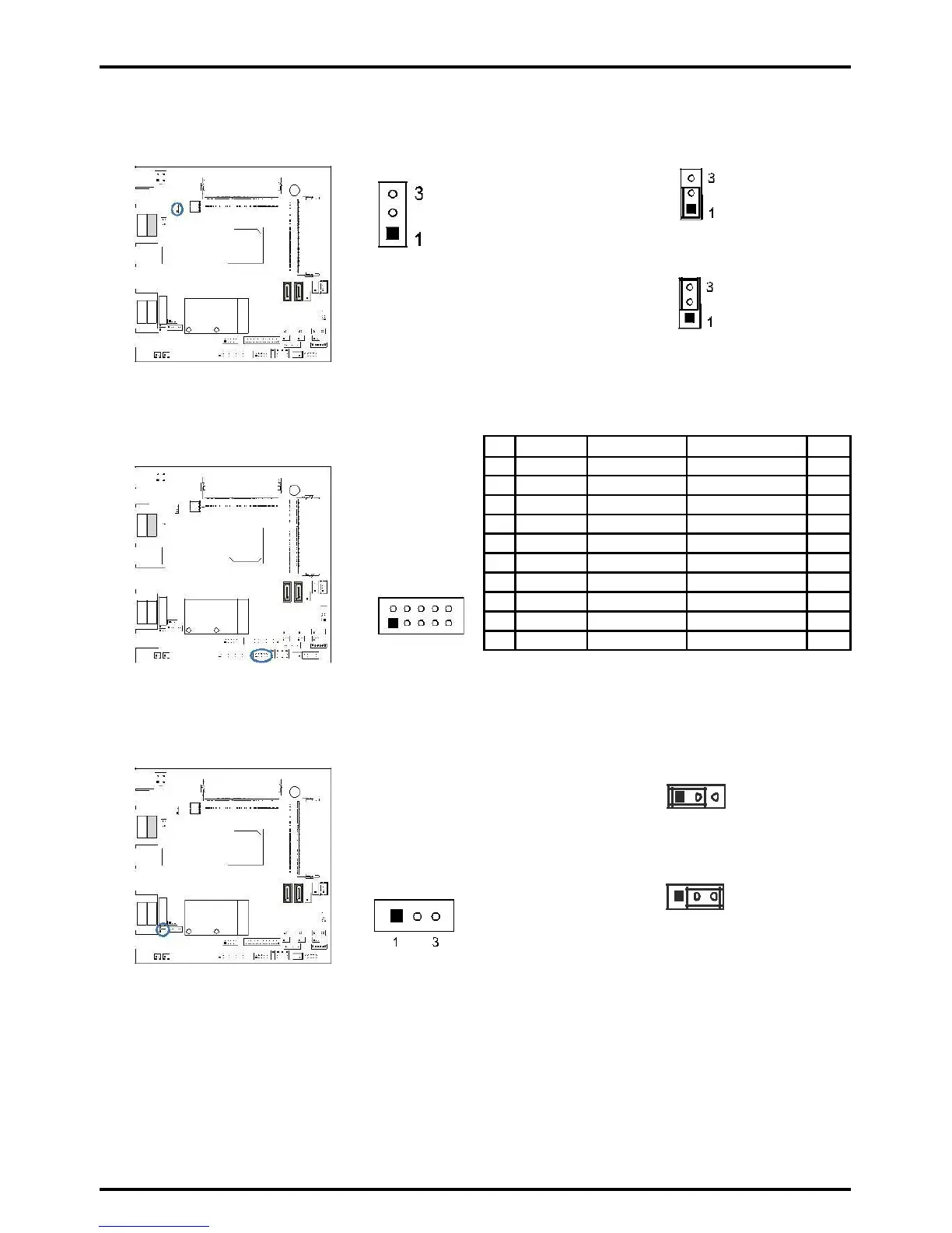
JP1: Voltage Switch Jumper for Cash Draw Connector
This jumper is for controlling the Pin4 of RJ11 (JRJ11) to switch 12V or 24V.
Pin 1-2 Close: Pin4 of RJ11(JRJ11)=24V
(Default)
Pin 2-3 Close: Pin4 of RJ11(JRJ11)=12V
JDIO1: Digital I/O Connector
This connector offers 4-pair of digital I/O functions and address is set in BIOS.
2
»»» You could read the address value at dword
(32 bits/4 bytes).
JMSRS1/JMSRS2: MSR Jumper
The jumpers enable or disable MSR connector function.
1 3
Pin 1-2 Close: JMSR1 Disabled (Default)
JMSRS1
JMSRS2
1 3
Pin 2-3 Close: JMSR1 Enabled
Chapter 2: Hardware installation | 17