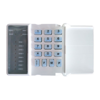
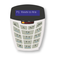
Connecting Magnetic Contacts and Panic Buttons to a Zone
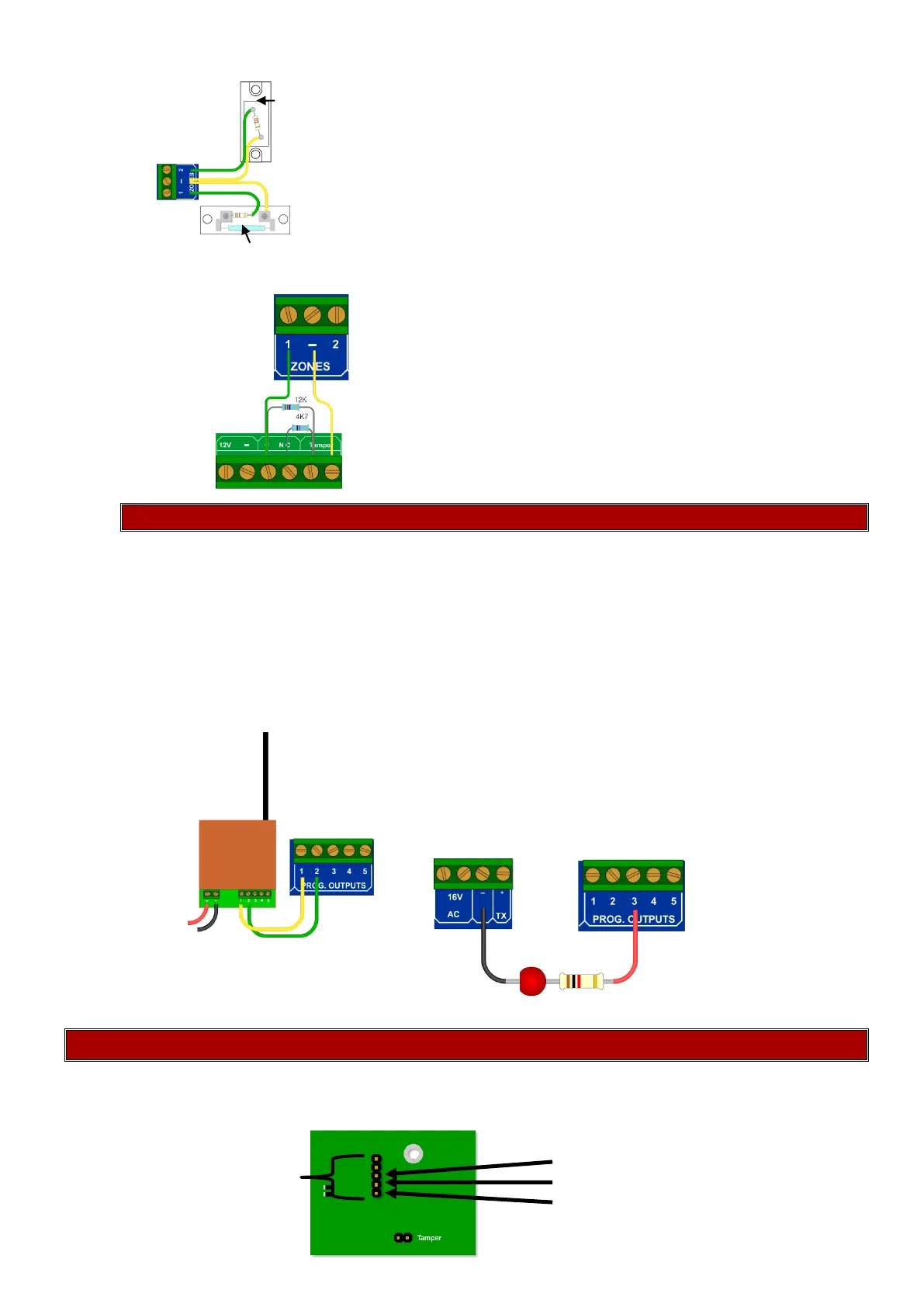
Tamper connection
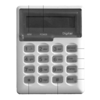
Programmable Outputs
Outputs are used to trigger other devices, with a positive 12V. The output can be either set to pulse
or latch.
Definition:
1. Pulse is when the output will go from no voltage up to 12V and with no intervention goes
back to no voltage. Like a spring if you compress it and then leave it alone it automatically
uncompresses.
2. Latch is when the output will go from zero to 12V and stay there until something else tells it to
go back to zero volts, like a light switch.
Serial Output (805S Only)
The serial connection outputs an IDS serial protocol that can communicate to any device which has the
protocol implemented. The serial connector can also be used to upload and download settings via
IDSwift2 and the IDS USB to Serial convertor.
Ground
Serial Connector Rx
Tx
The diagram shows a magnetic contact (NC) and a panic button (NO)
connected to a zone
Radio connected to output
 Loading...