Do you have a question about the IEMCA BOSS 332 and is the answer not in the manual?
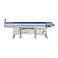
| Bar Capacity (Round) | 3 - 32 mm |
|---|---|
| Pusher Type | Hydraulic |
| Type | Automatic Bar Feeder |
| Control System | CNC |
| Power Supply | 400V / 50Hz |
Outlines safety regulations applicable to the bar feeder.
Details the warranty terms and conditions for the bar feeder.
Explains the objective and scope of the user manual.
Provides information on identifying the manufacturer and the bar feeder.
Guides on how to request technical assistance and provide necessary details.
Lists the documents included with the bar feeder manual.
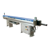
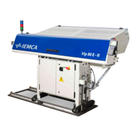
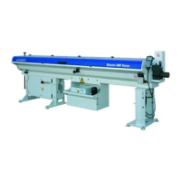
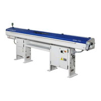
Provides an overall description of the automatic bar feeder and its capabilities.
Details the sequence of operations performed by the bar feeder during automatic cycles.
Describes the various safety devices incorporated into the bar feeder system.
Explains the meaning and location of safety warning plates on the machine.
Details different models and versions of the bar feeder, including bar length specifications.
Presents comprehensive technical specifications, dimensions, and performance data.
Outlines fundamental safety rules for operating and maintaining the bar feeder.
Covers safety precautions during the handling and installation process.
Highlights safety considerations for adjustments and setup procedures.
Provides essential safety guidelines for the daily use and operation of the bar feeder.
Details safety protocols to be followed during maintenance operations.
Describes the different packaging options for the bar feeder.
Provides instructions and safety warnings for lifting and handling the bar feeder.
Specifies requirements for the installation area, including dimensions and environmental factors.
Step-by-step guide for installing the bar feeder without the axial displacement feature.
Step-by-step guide for installing the bar feeder with the axial displacement feature.
Instructions for installing devices for sliding headstock lathes.
Instructions for installing devices for cam lathes.
Details the procedure for filling the lubrication oil system.
Covers the procedures and safety aspects of electrical connections.
Explains how to connect the pneumatic system to the bar feeder.
Guides on parameterizing the bar feeder software for specific needs.
Introduction to the adjustment and setup procedures for the bar feeder.
Covers general adjustments necessary for maintenance or troubleshooting.
Instructions for setting up the bar feeder based on the bar material and dimensions.
Details the procedure for timing the cam box and its microswitches.
Describes the functions and operation of the bar feeder's control system.
Explains the layout and functions of the handheld keyboard controls.
Describes the meaning of various light indicators on the bar feeder.
Covers features of bars and preparation steps required before machining.
Guides on initial setup and starting the automatic cycle of the bar feeder.
Explains how to stop the bar feeder, both in emergency and normal operation.
Procedure for restarting the automatic cycle after manual operations.
Steps to resume automatic operation after a power interruption.
A quick guide for changing machining types, with or without guide channel changes.
General safety rules and recommendations for performing maintenance.
Outlines a schedule for routine maintenance tasks and their frequencies.
Instructions on how to use and disengage the axial displacement device.
Lists common general failures, their causes, and troubleshooting solutions.
Addresses issues related to the bar magazine and bar loading.
Discusses failures encountered during feeding into the collet and their solutions.
Covers failures related to the bar feeding process and corrective actions.
Details the procedure for replacing the feeding chain, noting complexity.
Instructions for replacing the guide channel opening belt.
Procedure for replacing guide channels with inserts and polyurethane guides.
Guides on replacing the PLC battery to prevent data loss.
Lists recommended spare parts subject to wear or breakage.
Provides guidance on safe machine dismantling procedures.
Relates bar diameter to guide channels, bar pusher, and revolving tips.
Details collet choices based on guide channel and bar pusher diameters.
Table for selecting revolving tips for specific guide channel diameters.
Table for selecting revolving tips for specific guide channel diameters.
Table for selecting revolving tips for specific guide channel diameters.
Table for selecting revolving tips for specific guide channel diameters.
Table to determine internal collet diameter for hexagonal bars.
Table to determine internal collet diameter for square bars.
Table for collet selection for hexagonal bars in inches.
Table for collet selection for round bars in inches.
Table for selecting ejectors for guide channels with diameter less than 30mm.
Table for selecting ejectors for guide channels with diameter greater than 32mm.
Table for selecting pipe collets.
Table for selecting collets for various bar sizes.
Table for boring collets for square and hexagonal bars.
Table for selecting collets for various bar sizes.
Table for selecting ejectors for guide channels with diameter 13-28mm.
Table for selecting pipe collets.
Table for selecting collets for various bar sizes.
Table for selecting collets for various bar sizes.
Table for selecting ejectors for guide channels with diameter 33-46mm.
Table for selecting ejectors for guide channels with diameter 52-86mm.
Table for selecting rings for collets.