18
8 Set-up
The device is ready for operation after application of the supply voltage and the
self-diagnosis.
► After installation and electrical connection, check whether the device operates
safely.
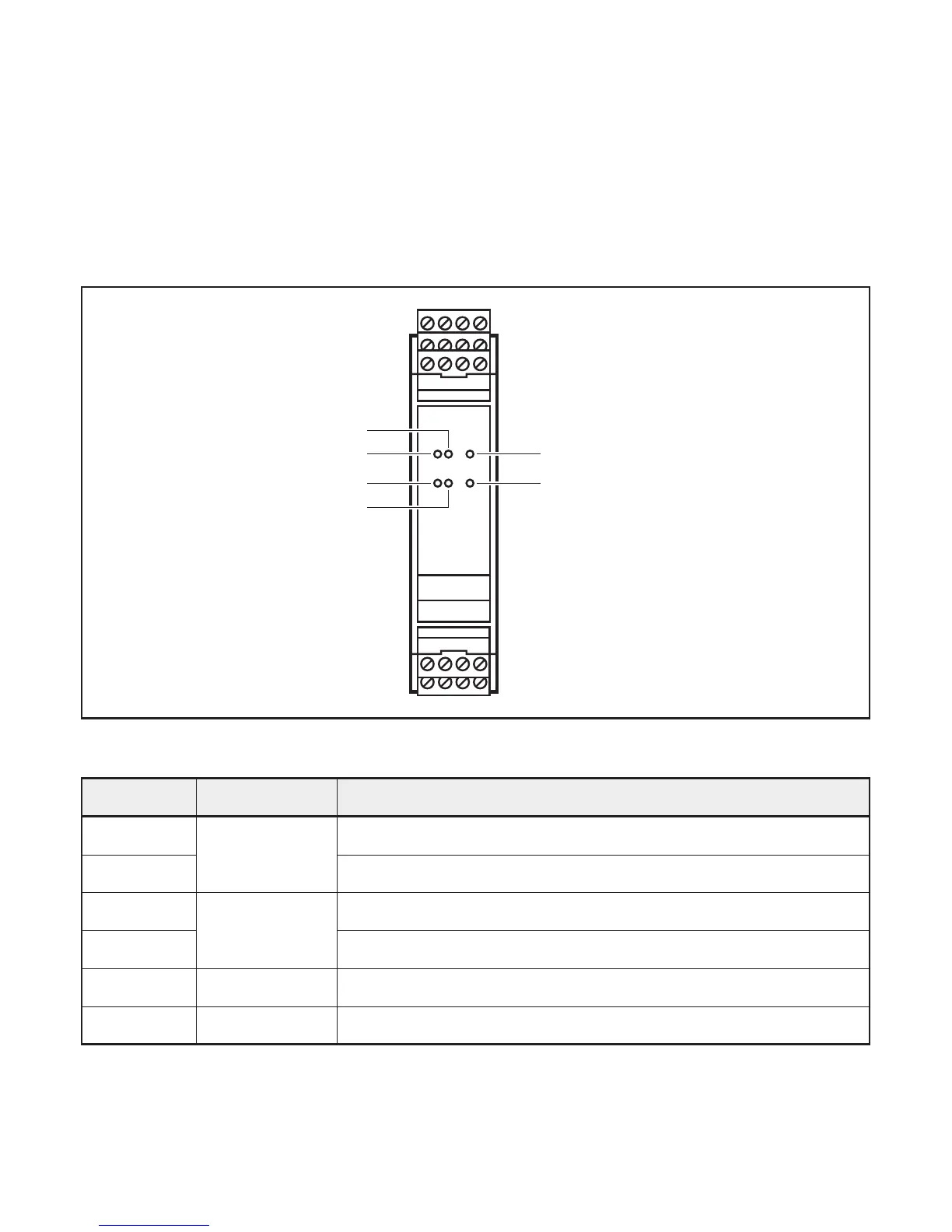
9 Display elements
E1
K1
K2
E2
Power
Fault
Display elements
LED Colour Meaning (normal operation)
E
1 Yellow Input signal channel 1
K
1 Output relay channel 1
E
2 Yellow Input signal channel 2
K
2 Output relay channel 2
Power Green Supply voltage
Fault Red Error
Detailedstatusdescriptionanderrordescription(→9.1LEDindicationsand
switching characteristics)