8
5 Function
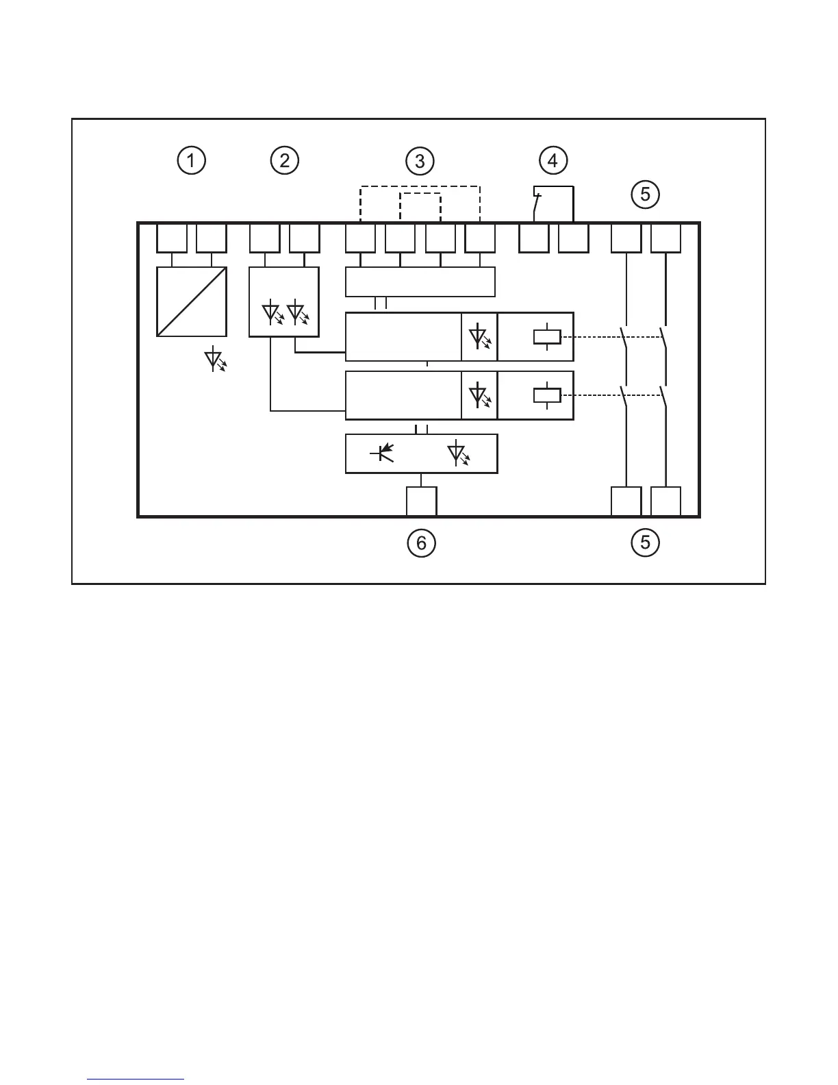
5.1 Block diagram
Y7 14 24
L+ L-
S34 S43
E124 V DC E2
S33
inputs switchpoint
DC
DC
power
controller 1
fault
S44
Y4 Y5 13 23Y4 Y5Y2 Y6
K1
controller 2
K2
1: Supply voltage
2: Inputs
3: Switch point setting (bridging)
4: Feedback contact
5: "Standstill" switching outputs
6: "Fault" transistor output
5.2 Operating principle
The device is a 2-channel pulse evaluation system for the safe detection of
underspeed or standstill. In this respect the device picks up the pulse sequences
of 2 connected pulse pick-ups.
The microprocessors calculate the resulting frequency. The device detects
underspeed as compared to the set switch point by constantly comparing the
frequency of the actual and the preset values.