5
UK
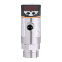
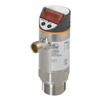
4 Function
4.1 Communication, parameter setting, evaluation
• The unit displays the current process value�
• It generates 2 output signals according to the parameter setting�
OUT1 •Switching signal for process value; IO-Link�
OUT2
2 options
•Switching signal for process value�
•Diagnostic signal (output 2 is inactive in case of a fault)�
• The following function is available via IO-Link (OUT1):
Reading the current process value, changing the parameters and transferring
them to other units of the same type using the FDT service program ifm Con-
tainer or other parameter setting tools with IO-Link capability�
The program library of the available DTM objects and the IO Device Descrip-
tion(IODD)areavailableatwww.ifm.com→Service→Download.
4.2 Switching function
OUTx changes its switching state if it is above or below the set switching limits
(SPx, rPx)� The following switching functions can be selected:
• Hysteresisfunction/normallyopen:[OUx]=[Hno](→fig.1).
• Hysteresisfunction/normallyclosed:[OUx]=[Hnc](→fig.1).
First the set point (SPx) is set, then the reset point (rPx) with the requested differ-
ence�
• Windowfunction/normallyopen:[OUx]=[Fno](→fig.2).
• Windowfunction/normallyclosed:[OUx]=[Fnc](→fig.2).
The width of the window can be set by means of the difference between SPx and
rPx� SPx = upper value, rPx = lower value�