7
UK
6 Electrical connection
The unit must be connected by a qualified electrician�
The national and international regulations for the installation of electrical
equipment must be adhered to�
Voltage supply to EN50178, SELV, PELV�
► Disconnect power�
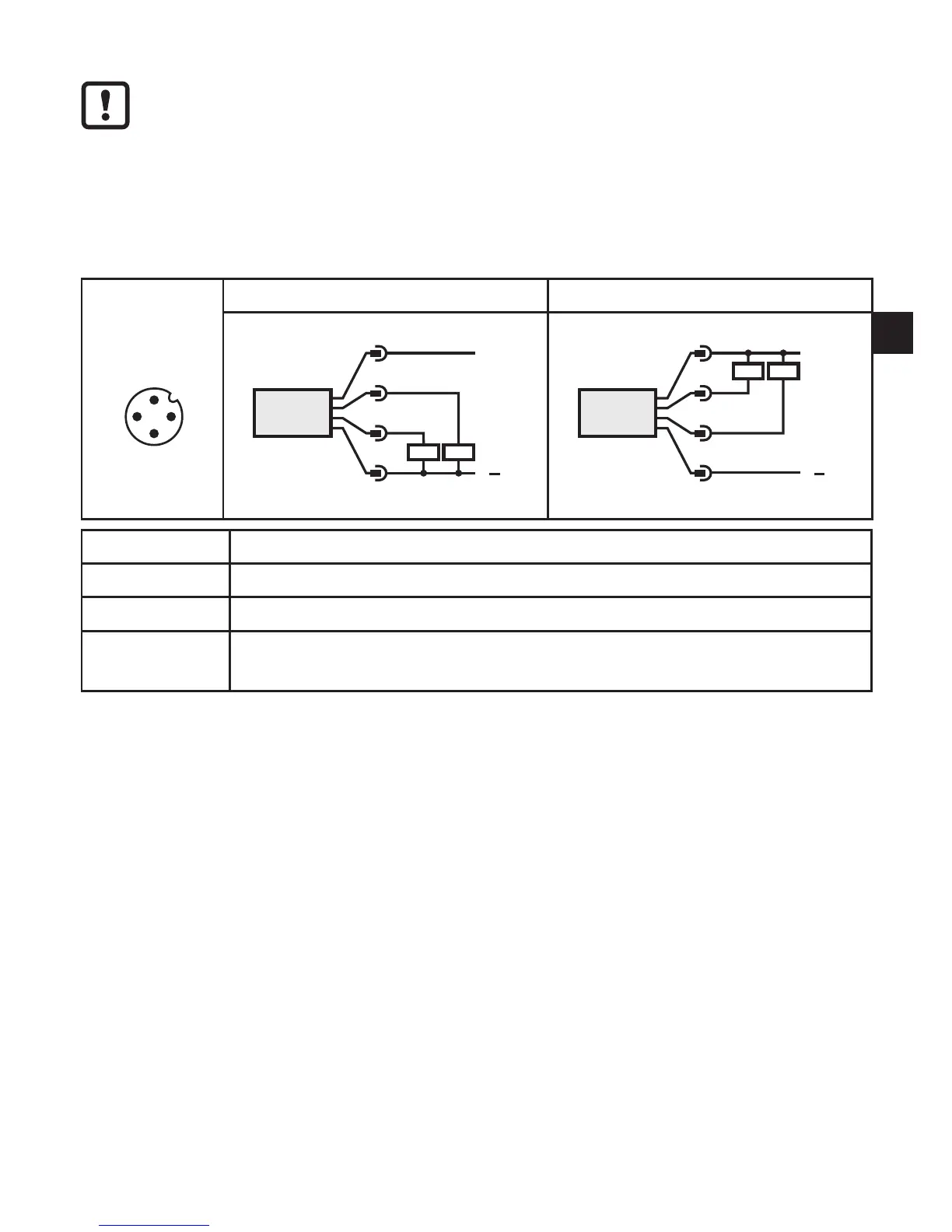
► Connect the unit as follows:
2 x p-switching 2 x n-switching
L
L
+
3 BU
4 BK
2 WH
1 BN
OUT 1 /
IO-Link
OUT 2
2:
4:
L
L
+
3 BU
4 BK
2 WH
1 BN
OUT 1 /
IO-Link
OUT 2
2:
4:
Pin 1 Ub+
Pin 3 Ub-
Pin 4 (OUT1) •binary switching output pressure monitoring; IO-Link
Pin 2 (OUT2)
•binary switching output if [OU2] = [Hno], [Hnc], [Fno] or [Fnc]
•diagnostic output if [OU2] = [dESI]
Core colours of ifm sockets:
1 = BN (brown), 2 = WH (white), 3 = BU (blue), 4 = BK (black)