Home
IFM
Accessories
LDH100
Page 8
IFM LDH100 - Page 8
11 pages
Manual
Save Page as PDF
To Next Page
To Next Page
To Previous Page
To Previous Page
Loading...
8
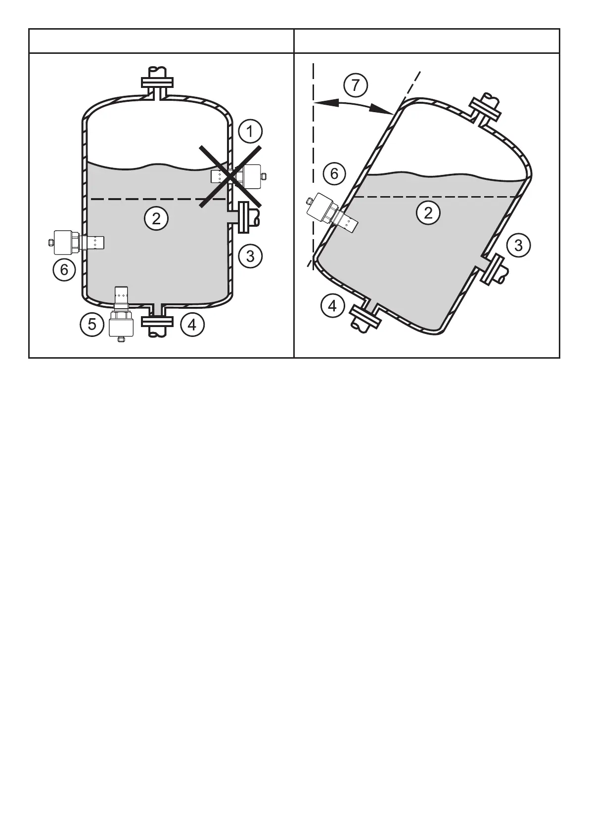
Fig. 1
Fig. 2
1:
W
rong installation position
2:
Minimum oil level in the tank
3:
Connection of the return pipe
4:
Connection of the rinse pipe
5:
Sensor vertically installed in the bottom
6:
Horizontally installed sensor
7:
Installation angle
7
9
Table of Contents
Main Page
Table of Contents
2
Symbols Used
2
Safety Instructions
3
Functions and Features
4
Function
4
4�1 Measuring Principle
4
4�1�1 Temperature Measurement
4
4�1�2 Humidity Measurement
4
4�1�3 Relative and Absolute Humidity
5
4�2 Processing of the Measured Signals
5
Installation
6
5�1 Typical Measuring System
6
5�2 Installation Location / Environment
7
5�3 Installation Procedure
9
Electrical Connection
10
Operation
11
Maintenance, Repair, Disposal
11
Related product manuals
IFM LMT100
25 pages
IFM LMT121
25 pages
IFM LW2720
44 pages
IFM LT80 Series
41 pages
IFM LMT 0 Series
25 pages
IFM efector 160 LR3000
38 pages
IFM OGD582
31 pages
IFM PN3 Series
29 pages
IFM O5H5 Series
5 pages
IFM OID20 Series
7 pages
IFM O5D10 Series
9 pages
IFM O1D100 series
4 pages