de
20
BEDIENUNGSANLEITUNG Gastroline www.igloo.pl
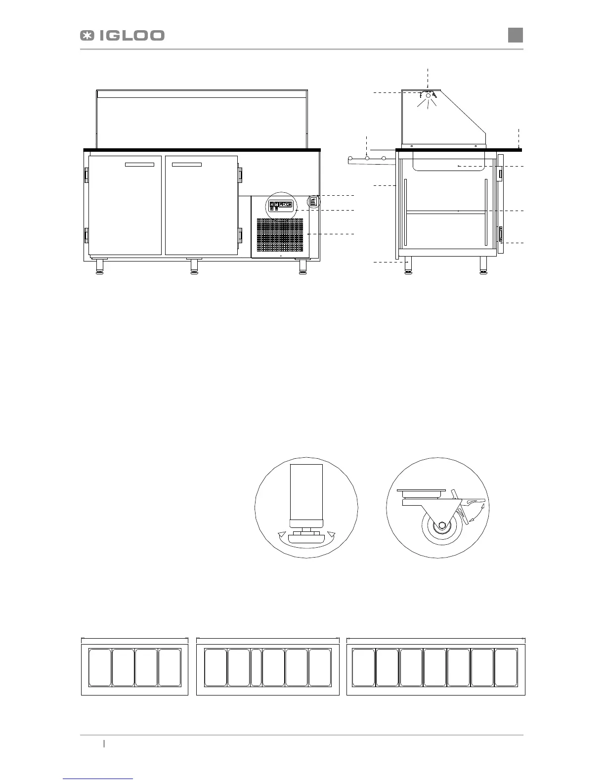
Abb.1 Bau der Anlage
1 – Glasregal
2 – Alulampe mit Beleuchtung
3 – Vorderregal für den Kunden
4 – Vorderseite der Vitrine
5 – Beinen zum Justieren der Anlage
6 – Granitblatt
7 – GN-Behälter
8 – Regal im Behälter
9 - Drehtüren
10 – Typenschild
11 – Steuerungspaneel der Vitrine
12 – Windkasten (nach dem Entfernen Zugang zu den Lamellen des Kondensats)
1 – Beinen die zum Justieren
2 – Fahrsatz (A – Fahrstellung;
B – Sperren)
Abb.3 Anordnung der GN-Behälter
Abb.2 Fest- und Fahrsatz
1500
GN
1/1
GN
1/1
GN
1/1
GN
1/1
Gastroline 1.5
2000
GN
1/1
GN
1/1
GN
1/1
GN
1/1
GN
1/1
GN
2/4
Gastroline 2.0
2500
GN
1/1
GN
1/1
GN
1/1
GN
1/1
GN
1/1
GN
1/1
GN
1/1
1
3
6
7
10
11
12
2
4
5
8
9
12
Gastroline 2.5
A
B