robolink
®
Joint kit – Documentation (#4; 2016-12)
igus
®
GmbH | Martin Raak | Tel. +49 (0)2203 9649 409 | mraak@igus.de 12
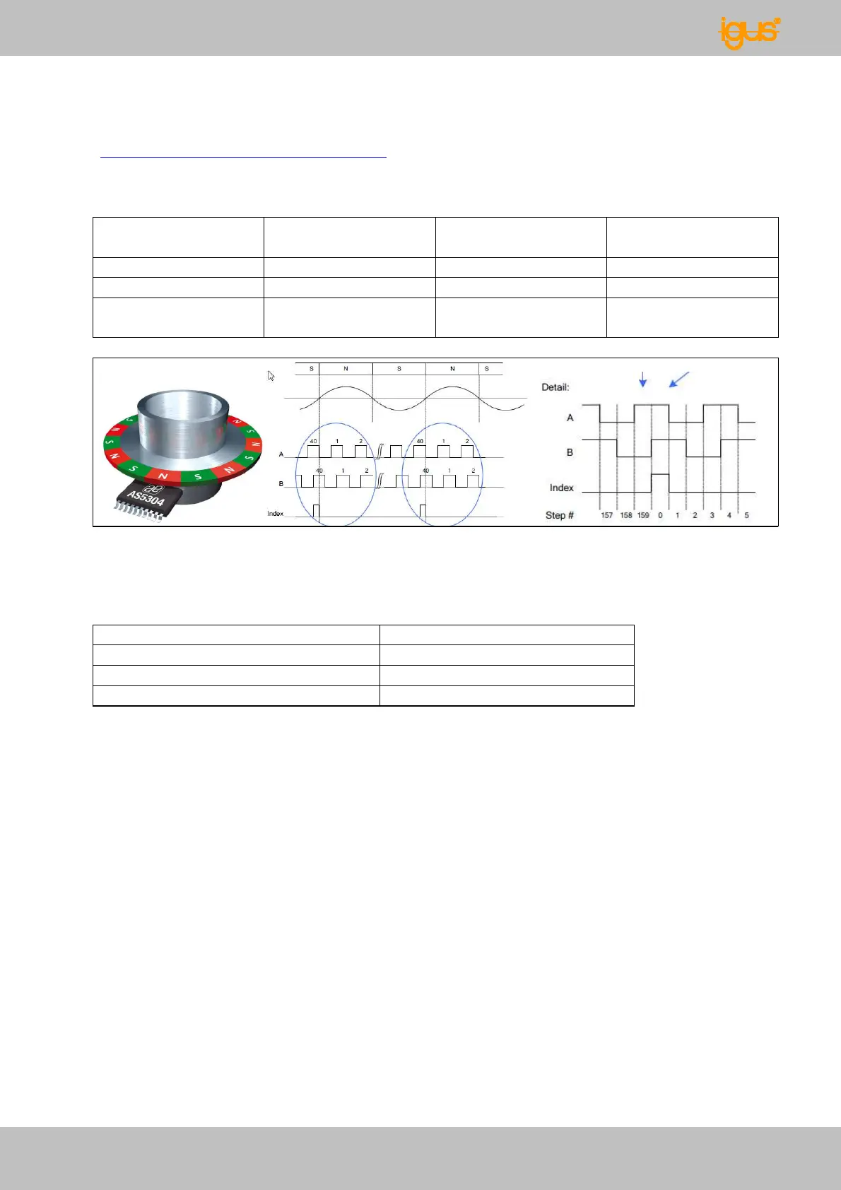
The encoder from Austriamicrosystems (=> Spec sheet download at
www.igus.de/robolink/support&service ) determines 4x40=160 A/B signals per pole pair.
This permits the following resolutions per axis:
chanel
(Quadratur)
Swivel RL-50-xxx 1.240 4.960 0,073°
Rotation RL-50-xxx 1.160 4.640 0,078°
Swivel / Rotation
RL90-xxx
2.480 9.920 0,036°
Fig. 25: A/B and index signals from the encoder
The resolution of the individual axis approximately corresponds to the following
positioning errors at the corresponding tube lengths:
Distance from center point (x) [mm] Positioning accuracy [mm]
200 0,24
400 0,49
500 0,61
Table 2: Positioning accuracy with angle sensors
Since the positioning errors for multiple axis are compounded, system designs have a
positioning inaccuracy, or repeatability accuracy of approx. 1-2mm for multi-axes systems
(depending on the number of axes and tube lengths).
The Hall Sensor Honeywell SS443A is used to reference the system (home position). It
has an Open-Collector-Output. This is designed for the connection to a TTL/CMOS-circuit
– the 10kΩ pull-up-resistance exists on the board already.
If the output has to be adapted to a 24V-circuit (e.g. PLC), it is realizable e.g. with the
following circuit diagram with an optical coupler device. The components have to be
adjusted to the respective loads. For this case, a possible electrical configuration is shown
in Fig. 26.