robolink
®
Joint kit – Documentation (#4; 2016-12)
igus
®
GmbH | Martin Raak | Tel. +49 (0)2203 9649 409 | mraak@igus.de 13
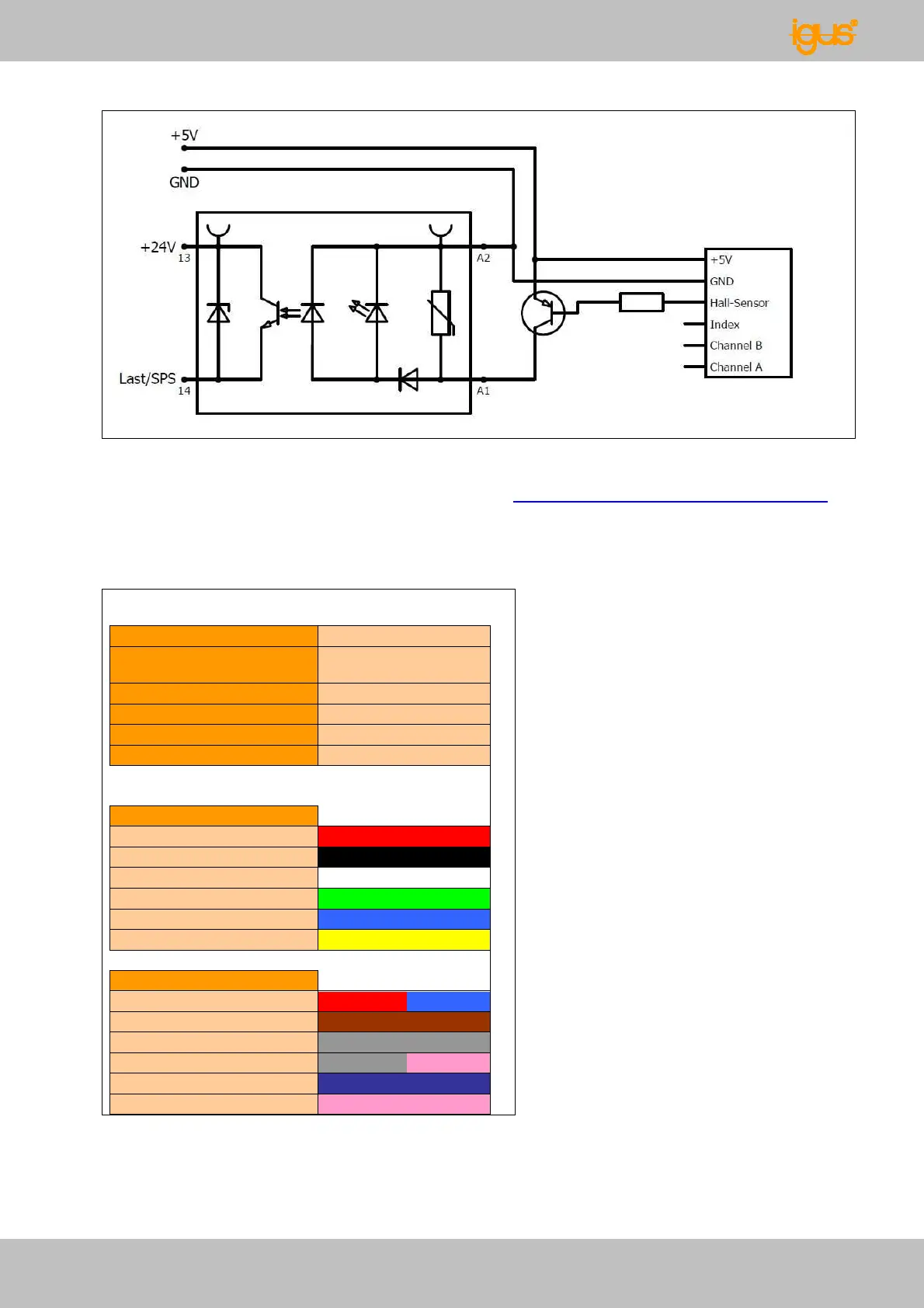
Fig. 26: Wiring the Hall sensors
Electrical circuit diagrams for the sensors are at www.igus.de/robolink/support&service .
Each joint axis must be reinitialized (homed) after a power failure.
Each axis (DOF) has 6 conductors. The corresponding strands are assigned as follows:
State
2012-08
producer
igus
line name
FIXFLEX
FF900.11.282
number of conductors
12
conductor cross section
0,09
line diameter [mm]
3,9
usage
from 04.2012
pivoting movement
+5V red
GND black
Hall-Sensor white
Encoder Index green
Encoder Channel A blue
Encoder Channel B yellow
turning movement
+5V red/blue
GND brown
Hall-Sensor grey
Encoder Index grey/rose
Encoder Channel A violet
Encoder Channel B rose
Fig. 27: Cable definition - igus
®
sensor cables