21
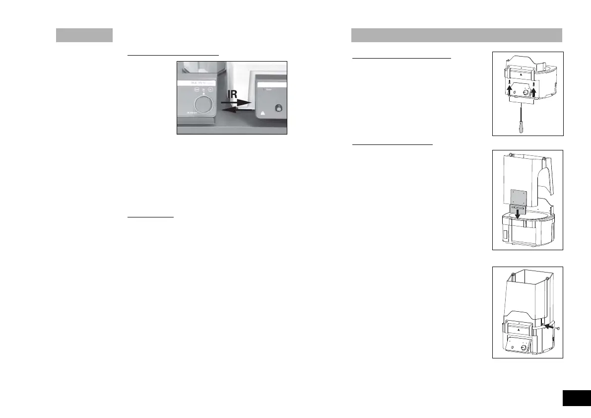
Assembly of spray guard and cover accessories
Assembly spray guard HB 10.1
☞ Assemble the spray guard as illustrated.
- Place the bracket of the spray guard on
the front edge of the heating bath.
- Attach the spray guard by tightening the
screws using a screwdriver.
Assembly Cover HB 10.2
☞ Assemble spray guard and cover as illust-
rated.
- Push the angled sheet on the back part of
the cover into the guide rails at the rear of
the heating bath.
- Screw the back and front part of the
cover to the spray guard.
Interface
Data transfer via IR interface
The heating bath transfers data via IR interfaces. These are loca-
ted on the left display side of the heating bath or on the right side
of the drive unit. Do not place any objects between the two ope-
rating units as otherwise the data transfer may be interrupted (fig.
14)!
Remote Mode
Using the laboratory device software “labworldsoft” and the rota-
ty evaporator RV 10 digital/ control the device can be operated in
“Remote” mode. In this mode, the device can no longer be hand-
operated.
➣ LCD display see fig. 10
Note: Please note the system requirements as well as the opera-
ting instructions and help section included with the software.
Fig.14
Fig.15
Fig.16
Fig.17
3946600_HB10bdc_032009:3345300_VG3_042005_kvmb_1 28.04.2009 9:23 Uhr Seite 21