5
• Unpacking:
- Please unpack the device carefully
- In the case of any damage a detailed report must be
sent immediately (post, rail or forwarder).
• Delivery scope:
LR 1000 basic:
- LR 1000 basic base
- Reactor vessel LR 1000.1 (see Fig. 4)
- Temperature sensor
- Receptacle for temperature sensor
- Support rod
- 2 pieces hose connectors
- Mains cable
- Tool kit (see Fig. 1)
- Operating Instructions
- Warranty card.
Unpacking
Fig. 1
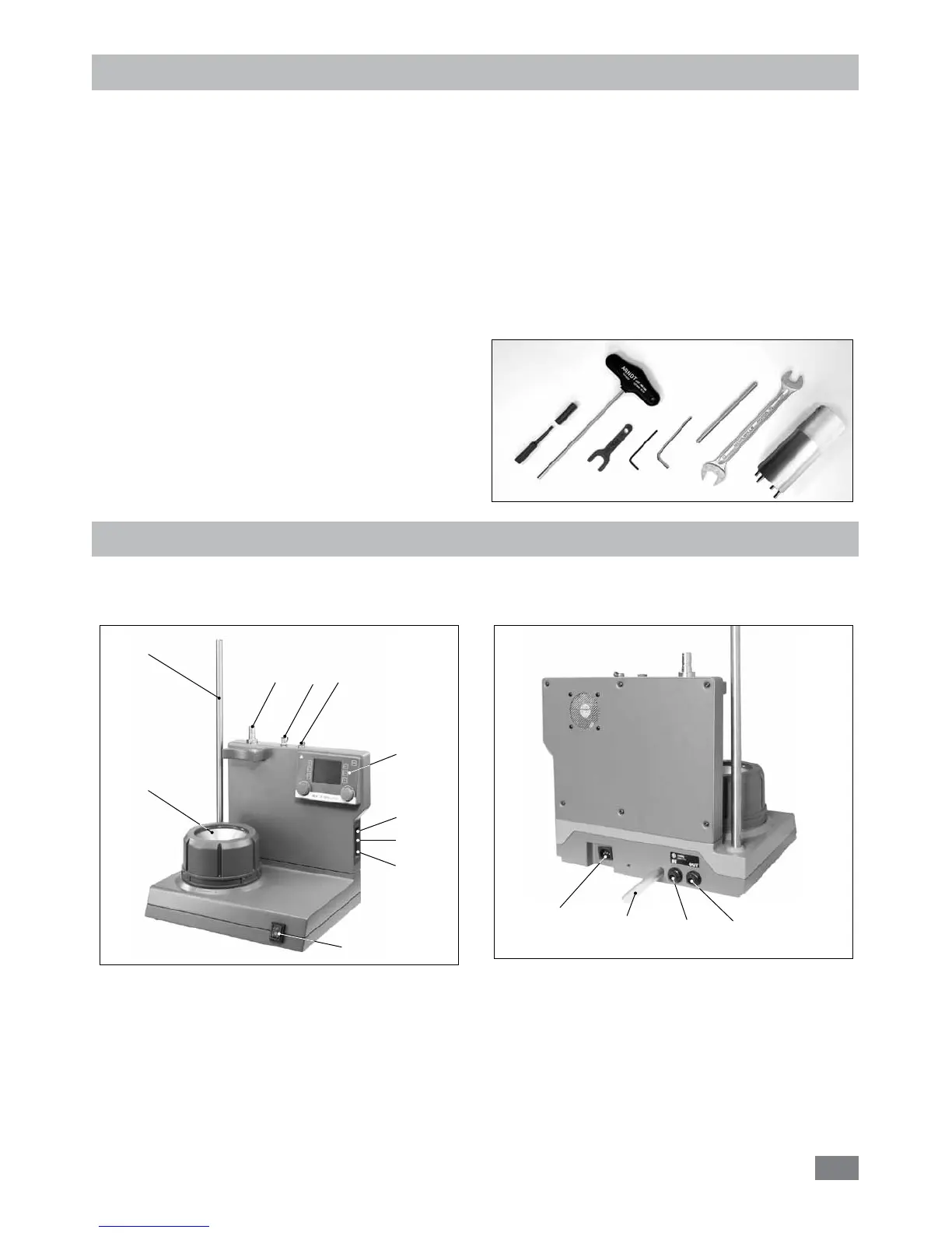
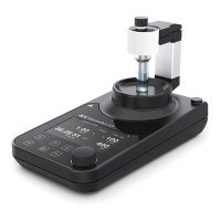
System configuration
IKA
®
LR 1000 basic/control laboratory reactor comprises:
• LR 1000 basic/control base:
1: Mains switch
2: Control elements and display
3: Heating block (with integrated cooling coils for
connecting external cooling systems)
4: Support rod, for securing accessories
5: Temperature sensor socket
6*: pH-probe socket (for LR 1000 control only)
7: Reception for disperser (Park station)
Fig. 2
4
1
3
2
57
8
9
10
Fig. 3
11
12
13
14
6*
8: Adjustable safety circuit
9: USB port
10: RS 232 port
11: Power socket
12: Condensate drain*
13: Cooling connection IN*
14: Cooling connection OUT*
*
Note: Cooling connections can be used only for cooling purpose.
LR 1000 control:
- LR 1000 control base
- Reactor vessel LR 1000.3 (see Fig. 5)
- Temperature sensor
- Receptacle for temperature sensor
- Support rod
- 2 pieces hose connectors
- USB cable
- Mains cable
- Tool kit (see Fig. 1)
- Operating Instructions
- Warranty card.