OPERATION
Front Panel Operation
03_10 LDX-36000 Series 35
CHAPTER 3
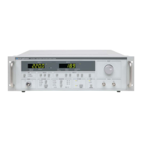
Configuring the Operational Mode
The LDX-36000 Series has two main operational modes
- CW (continuous wave) and QCW (quasi-continuous
wave or pulsed). The currently selected operating mode
may be identified in two ways. Either the CW or QCW
LED will be illuminated in the mode selection box in the
lower right-hand section of the front panel as shown in
Figure 3.8. In addition, one of the LEDs in either the CW
Mode box or the QCW Mode box will be illuminated to
specify which type of mode is selected. To switch
between CW and QCW modes, the operational mode
selection button must be pressed twice.
Figure 3.9 Mode Selection
Adjusting Current Setpoint
Press the I button in the Display 1 Adjust box (Figure 3.5) to display laser current
setpoint in Amps. Next, rotate the Adjust knob to the current setpoint required. If
no other button is pressed, the Adjust knob will remain active to allow adjustments
to the current without any intervening keypresses. However, if any other button is
pressed (with the exception of the P/P
PD
button), the I button must be pressed
again before drive current can be changed. In the case of the P/P
PD
button, drive
current is being adjusted in the “background” in an effort to change the output in
terms of optical power.
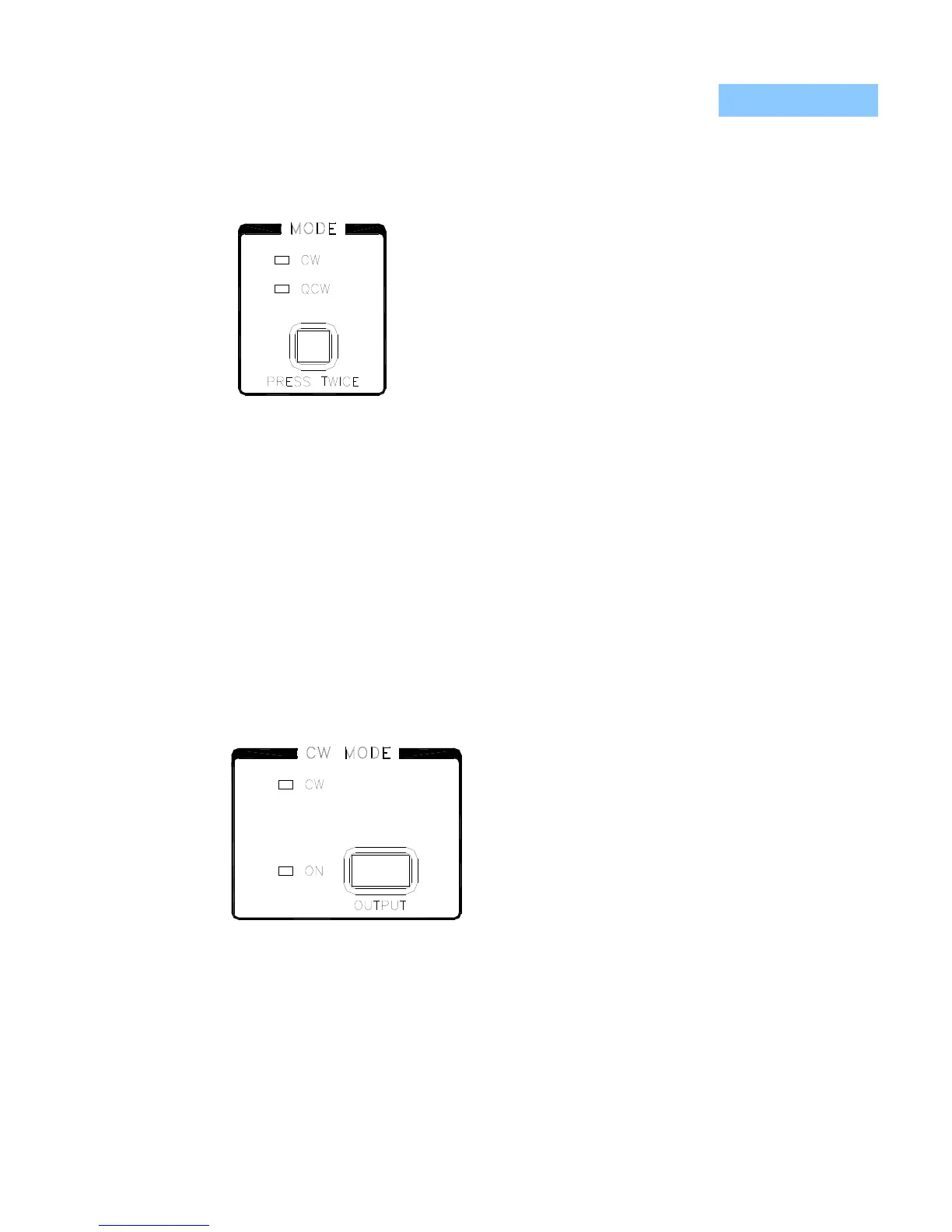
Enabling CW Output
CW current output is enabled by pressing the
Output button in the CW Mode box shown in
Figure 3.9. Once pressed, there is a two
second delay before output is actually enabled.
This is a required safety feature and cannot be
disabled. During this waiting period, the output
ON LED will flash. After the two second delay,
the output shorting relays will open, the output
will be enabled and the LED will stop flashing
and remain on.
Figure 3.10 CW Mode Box
Note: After the initial two second delay, the current will be ramped up to the set point in
discrete steps. During this time, a safe operating voltage is calculated and set by the
instrument controller. The step size during the ramp is a function of full scale output current
and set point current and is controlled by the instrument. The ramp cannot be adjusted
through the instrument’s front panel or GPIB commands.
 Loading...