OPERATION
Front Panel Operation
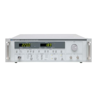
03_10 LDX-36000 Series 39
CHAPTER 3
Note: The left-hand P
w
button, in conjunction with the % button, denotes operation in
constant duty cycle and is indicated by the Const % LED below Display 2. This implies that
when pulsewidth is varied, the current value for duty cycle will remain constant and pulse
frequency will change as appropriate until the frequency reaches its maximum or minimum
limit. For example, with a duty cycle of 5%, the pulsewidth cannot be set smaller than 50
µs as this would cause the pulse period to go below 1 ms and frequency to exceed 1 kHz
which is the maximum value allowed.
Pressing the right P
w
button configures Display 2 to show QCW pulsewidth
setpoint as well. The difference being that now, operation is in terms of constant
frequency or pulse rate. This is verified by the illumination of the Const Freq LED
below Display 2. Pressing the Adjust button allows pulsewidth to be varied, but
with the duty cycle changing as required to maintain the currently set value for
frequency.
Note: Maximum frequency under any condition in QCW Pulse Mode is 1 kHz.
Note: Refer to Appendix A for allowed duty cycle and frequency combinations with varying
pulsewidth.
QCW-Trig Mode
QCW-Trig mode is selected by pressing the QCW-Mode Select button (Figure
3.10) until the TRIG LED is illuminated. In this mode, pulsewidth is configurable
from the front panel or through GPIB. An output pulse of this specified pulsewidth
will be output whenever a trigger signal is received at the Trigger Input BNC. The
output pulse may be delayed by a value specified through GPIB. The output
pulse is triggered on the rising edge of the TTL input trigger pulse.
A TTL-level (50 ) output trigger will be output from the Trigger Output BNC for
each current pulse produced regardless of QCW operational mode. This trigger
pulse may be delayed from the output pulse by a value specified through GPIB as
well. Refer to Figure 3.11 for a QCW timing diagram which shows the relationship
between the delays and the current pulse.
In this mode, duty cycle percentage and frequency displays are disabled.
Pressing the % or Freq button will result in dashes "- - -" being shown in Display 2.
If the frequency of the external trigger exceeds 1 kHz, the instrument will ignore the next
rising edge. The output pulse will be limited to 1 kHz.
 Loading...