OPERATION
Front Panel Operation
36 LDX-36000 Series
CHAPTER 3
QCW (Pulsed) Mode Setup
Quasi-CW (QCW) mode allows the output to be pulsed in three different
configurations: internally triggered (PULSE), externally triggered (TRIG), or hard
pulse. In QCW-Pulse and hard pulse modes, all parameters - pulsewidth, duty
cycle and/or frequency, are set via the front panel or through GPIB. In QCW-Trig
mode, pulsewidth is set from the front panel or GPIB and a pulse is output
whenever a trigger is received from the front panel Trigger Input BNC.
Note: In all QCW modes, a TTL pulse of ~10 µs width will be output from the Trigger
Output BNC with every output current pulse. The TTL pulse may be delayed from the
current pulse by an amount specified by GPIB.
Note: In all QCW modes, a TTL pulse will be output from the rear panel Ext Pulse Out
BNC with a width matching the output current pulse.
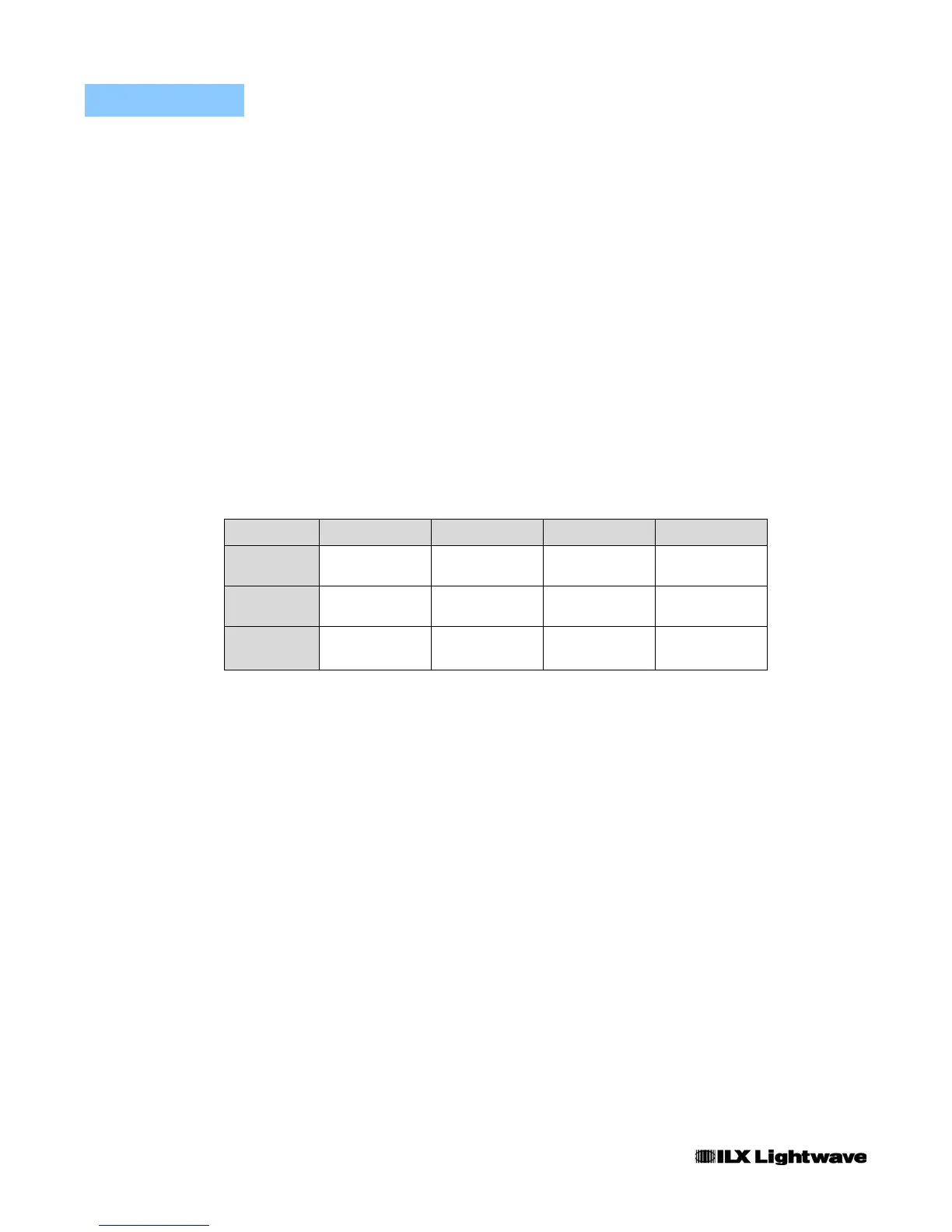
Table 3.4 summarizes the various QCW modes and how the parameters may be
configured.
Note: In all QCW modes, current setpoint remains configurable only from the front panel or
via GPIB.
QCW mode is entered by pressing the Mode button (Figure 3.10) twice to switch
from CW to QCW mode. Once the QCW operational mode has been enabled, the
last enabled QCW mode LED will be illuminated.
There are two current ramp features built into the LDX-36000 Series drivers when
pulsing high power laser diodes in either QCW mode or HPulse mode. When the
output is first enabled with the “OUTPUT” push button, there is a two second
delay followed by a current ramp consisting of discrete steps until the set point
current is reached (see Figure 3.10). The current ramp starts from a small current
of 0.5 amps increasing to 0.7 to 1 amp depending on the model and the
instrument mode of operation. During this time a safe operating overhead voltage
is calculated and set by the instrument controller. The current ramp continues up
to a maximum value of 10A depending on the set point and the load voltage. For
example, if the LDX-36125-24 QCW pulse mode set point is 220 amps, when the
output is enabled and following the two second delay, the current output will be
ramped to 0.5 amp, then 1.0 amp and finally increasing by 10 amp steps until the
set point of 220 amps is reached.
Table 3.4 Configuring QCW Parameters
QCW Mode Output Current Pulsewidth Duty Cycle Frequency
PULSE Front Panel /
GPIB
Front Panel /
GPIB
Front Panel /
GPIB
Front Panel /
GPIB
TRIG Front Panel /
GPIB
Front Panel /
GPIB
Trig In Trig In
HARD
PULSE
Front Panel /
GPIB
Front Panel /
GPIB
Front Panel /
GPIB
Front Panel /
GPIB
 Loading...