K2950SCHEDESS_01 – K2950SCHEDESS_02 (E141203X)
5
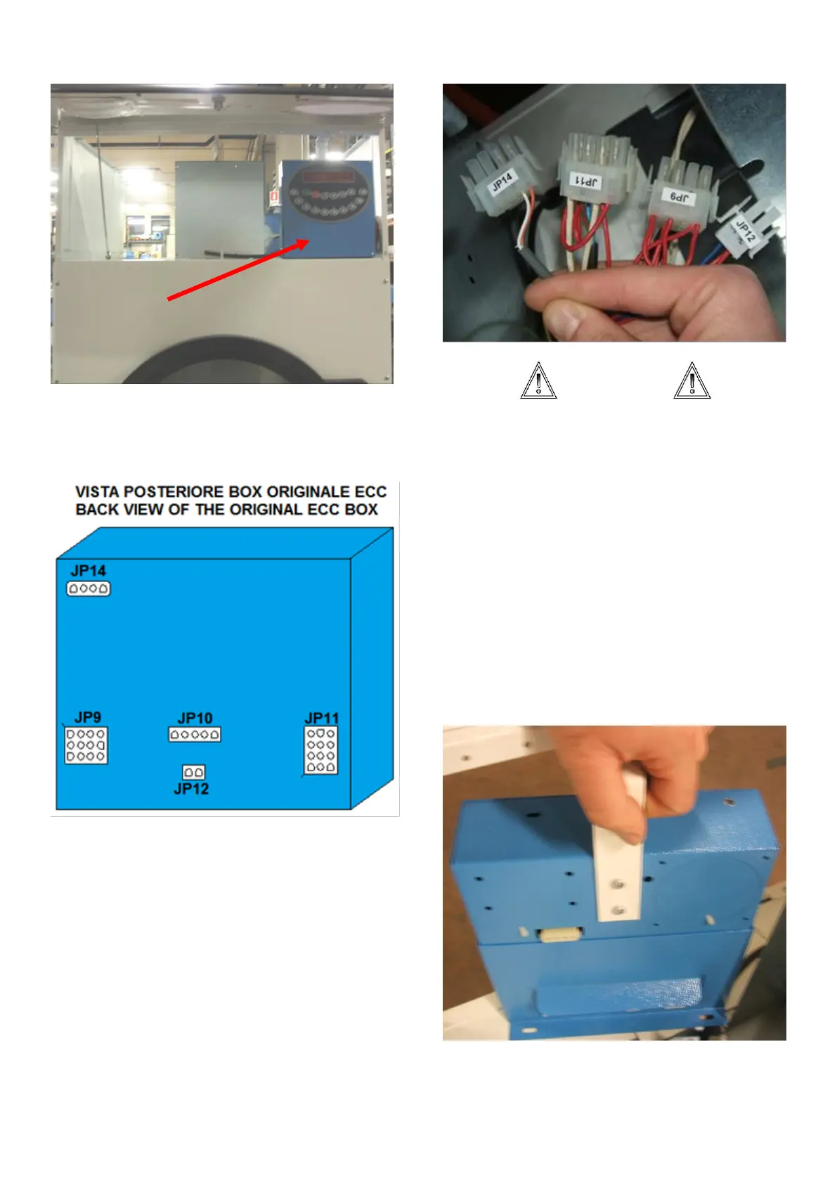
Before to remove the ECC box, label the
male connectors (the ones with the cables)
as shown below:
ATTENZIONE
JP9 and JP11 are both 12 ways
connectors. To distinguish between one
and the other connector, check where the
door sensor back cable is addressed. The
door sensor is contained only in the JP11
connector. To check the detailed list of the
connectors, see last paragraph of this
instructions.
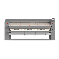
c) Remove the programmer box from the
above room. It is fixed by three self-drilling
cross headed screws: two at the base, on
the above bracket.