IMI Sensors: A PCB Piezotronics Div 699A07 User Manual
MAN-0192 rev A Page 25 of 39 800-959-4464
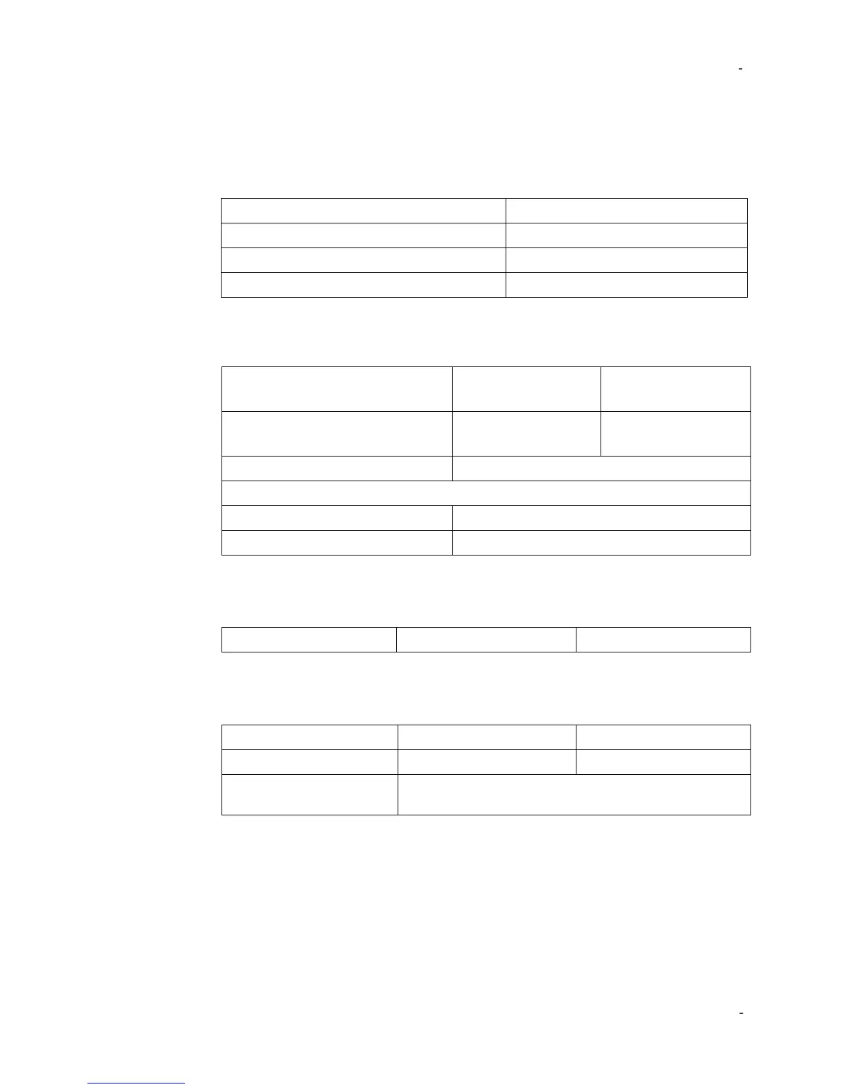
SUT Specifications
Power Requirements
Internal Battery
(sealed gel lead acid)
AC Power (for recharging battery)
110 – 240 VAC,
50 - 60 Hz
110 – 240 VAC,
50 - 60 Hz
Input Power Rating for charger
Operating Battery Life
[3]
100 gram payload, 100 Hz, 1 g pk
100 gram payload, 100 Hz, 10 g pk
[3] As shipped from factory in new condition
Temperature
Sensor Mounting Platform
Thread Size
Shaker Loading
Maximum advisable vibration levels are dependent upon the maximum frequency of
operation and the payload. The chart below shows the maximum vibration levels as
a function of both frequency and payloads. Payloads exceeding 800 gram should
not be tested on the Model 699A07.
Excessive loads may result in damage to the moving coil and flexure. Care must be
taken when testing payloads with large footprints, particularly those with an offset
SUT Bias offset measurement range
SUT Bias fault Voltage limits
 Loading...