IMI Sensors: A PCB Piezotronics Div 699A07 User Manual
MAN-0192 rev A Page 37 of 39 800-959-4464
a. One full rotation of the micrometer is 25 mils. To accomplish step 6 quickly,
complete three full rotations of the micrometer and then move 5 more mils.
7. All data is now entered, press View Certificate to view, edit, save and print the report.
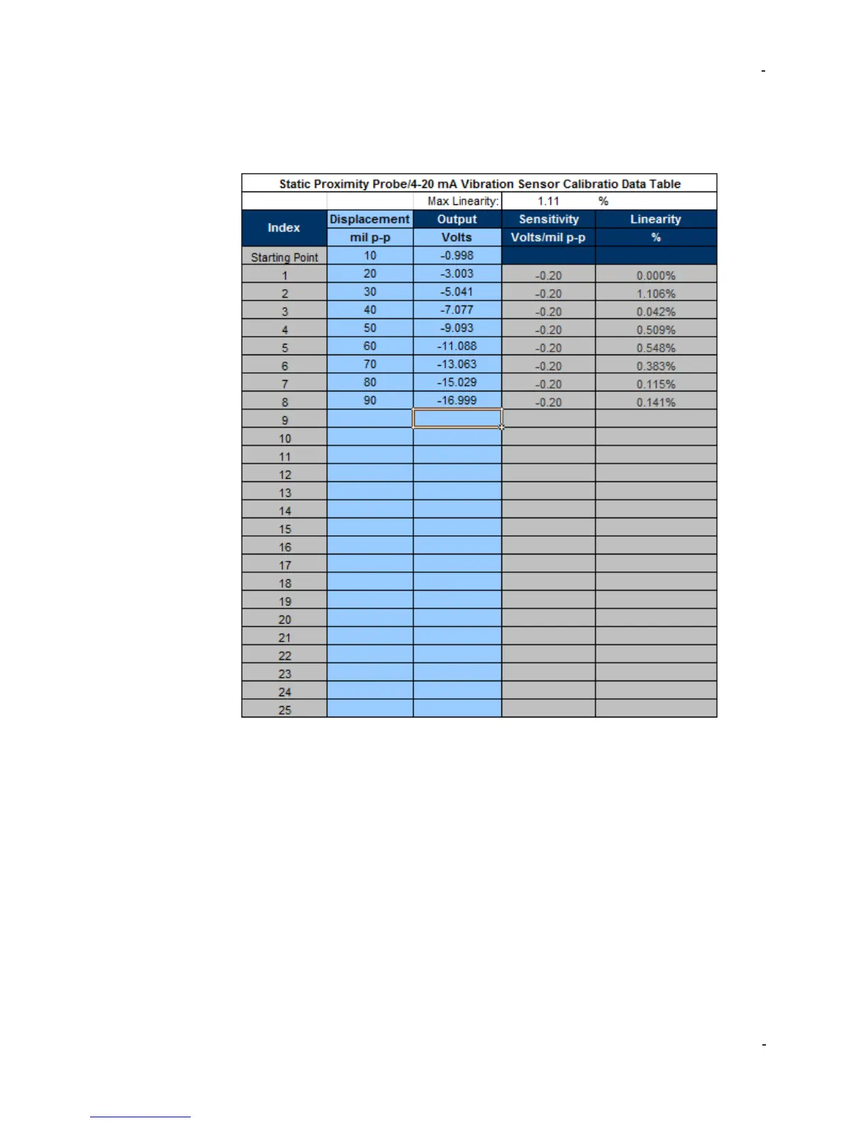
Testing 4-20 mA Vibration Transmitters
Loop-powered 4-20 mA vibration transmitters give an overall vibration level reading
and interface directly with the plant PLC, DCS or SCADA system just as process
instrumentation does. The most important function of these sensors and the control
system to which they are connected is the vibration alarms:
1. Remove the vibration transmitter from the machine and mount to the shaker table.
Users may need a mounting adaptor such as ¼” NPT available from IMI Sensors.
The shaker table should be brought to the sensor.
2. Leave all connections as is this will test the sensor, cable, system, display and
alarms.
3. Set the frequency to the running speed of the machine. It may be easier to use the
CPM scale than Hz for this test (press frequency dial and enter sub-menu to
change)
 Loading...