IMI Sensors: A PCB Piezotronics Div 699A07 User Manual
MAN-0192 rev A Page 30 of 39 800-959-4464
the accelerometer. Its accuracy is important at many frequencies. Test to Fmax on
the vibration analyzer. If high frequency bearing fault detection methodologies are in
use, test the sensor to the highest possible bearing defect frequency.
o Tip: Magnetically mounting sensors greatly reduces high frequency
response. A ferrous magnet target, mounting pad 080A118, is included
with the 699A07. One can install this pad on the shaker and mount
accelerometers magnetically. Always rock the sensor in place as one
would on the machine. Test the accelerometer to Fmax on the analyzer to
see if response is amplified at relevant high frequencies.
Calibrating Charge-Mode Accelerometers
The output of charge-mode accelerometers is in pico-coulombs per g (pC/g). The
“Test Sensor Input” of Model 699A07 can only read AC voltage or current. Charge-
mode accelerometers can be tested with the Portable Vibration Calibrator if their
signal is first conditioned to mV units using an single-ended or differential charge
amplifier.
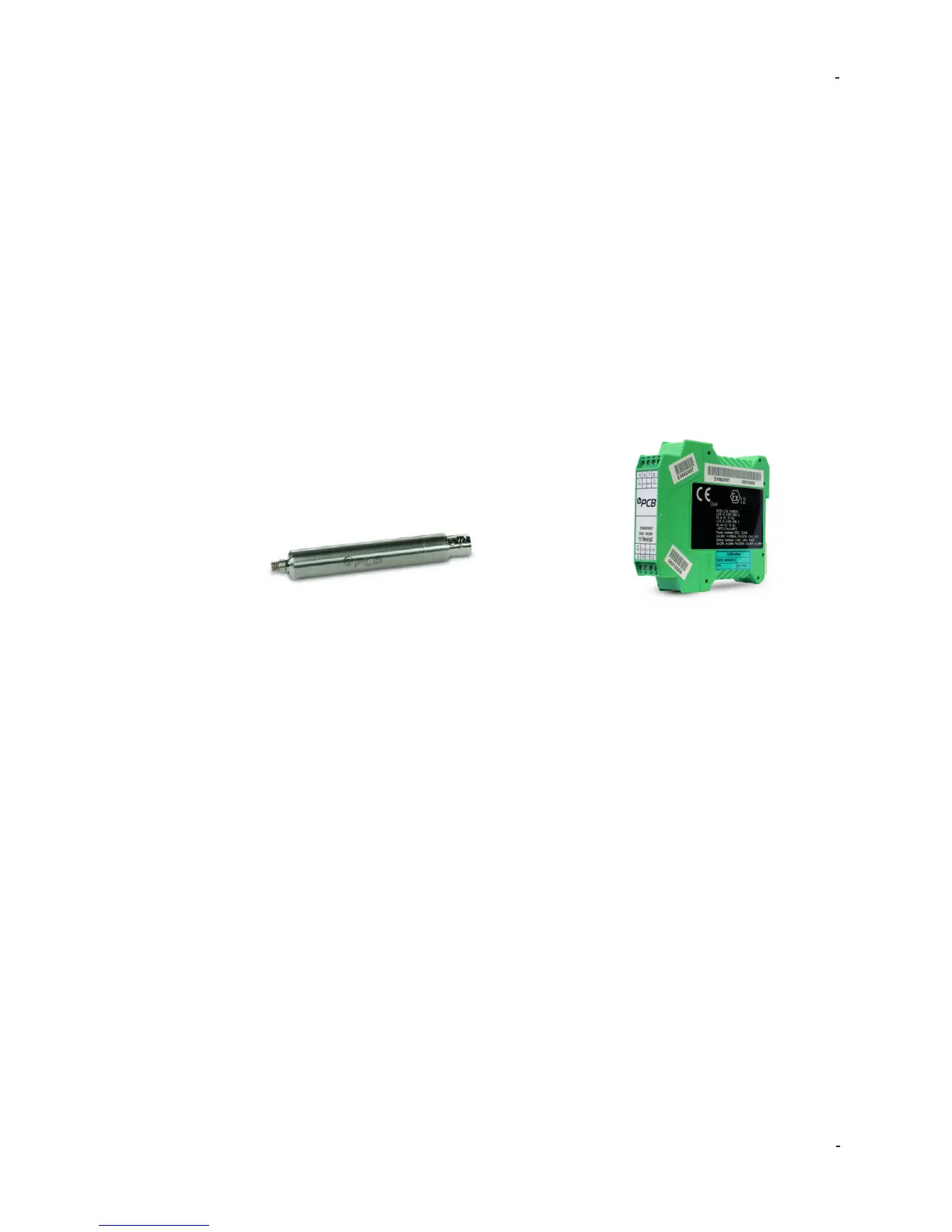
Model 422E3X Model EX682A40
Single-Ended Charge Amp Differential Charge Amp
First, make sure ICP® Input Mode is selected. When the charge-mode
accelerometer is connected to a charge amp and then connected to “Test Sensor
In”, the 699A07 will display the calibrated system sensitivity (i.e. the sensitivity of the
sensor-amp combination). For example, if a 10 pC/g accelerometer is used with a
10 mV/pC charge amplifier, the nominal system sensitivity is 100 mV/g:
10 pC/g * 10 mV/pC = 100 mV/g
Users can create calibration certificates in pC/g units in the Report Generation
Workbook. Simply check the box at top left of the FRData tab in the Report
Generation Workbook to create calibration certificate in pC/g. Next, enter the
sensitivity of the charge amplifier in mV/pC in cell D8. Finally, import the calibration
data and view certificate as describes in the “Report Generation Workbook” section.
The resulting calibration certificate will be in pC/g, removing the effect of the in-line
charge amplifier.
Non-Contact Displacement Sensor Calibration
Non-contact displacement sensors, also known as proximity probes, eddy current
probes or displacement probes, can be checked for accuracy, linearity, and
frequency response. Proximity probe systems require the use of the optional
 Loading...