IMI Sensors: A PCB Piezotronics Div 699A07 User Manual
MAN-0192 rev A Page 21 of 39 800-959-4464
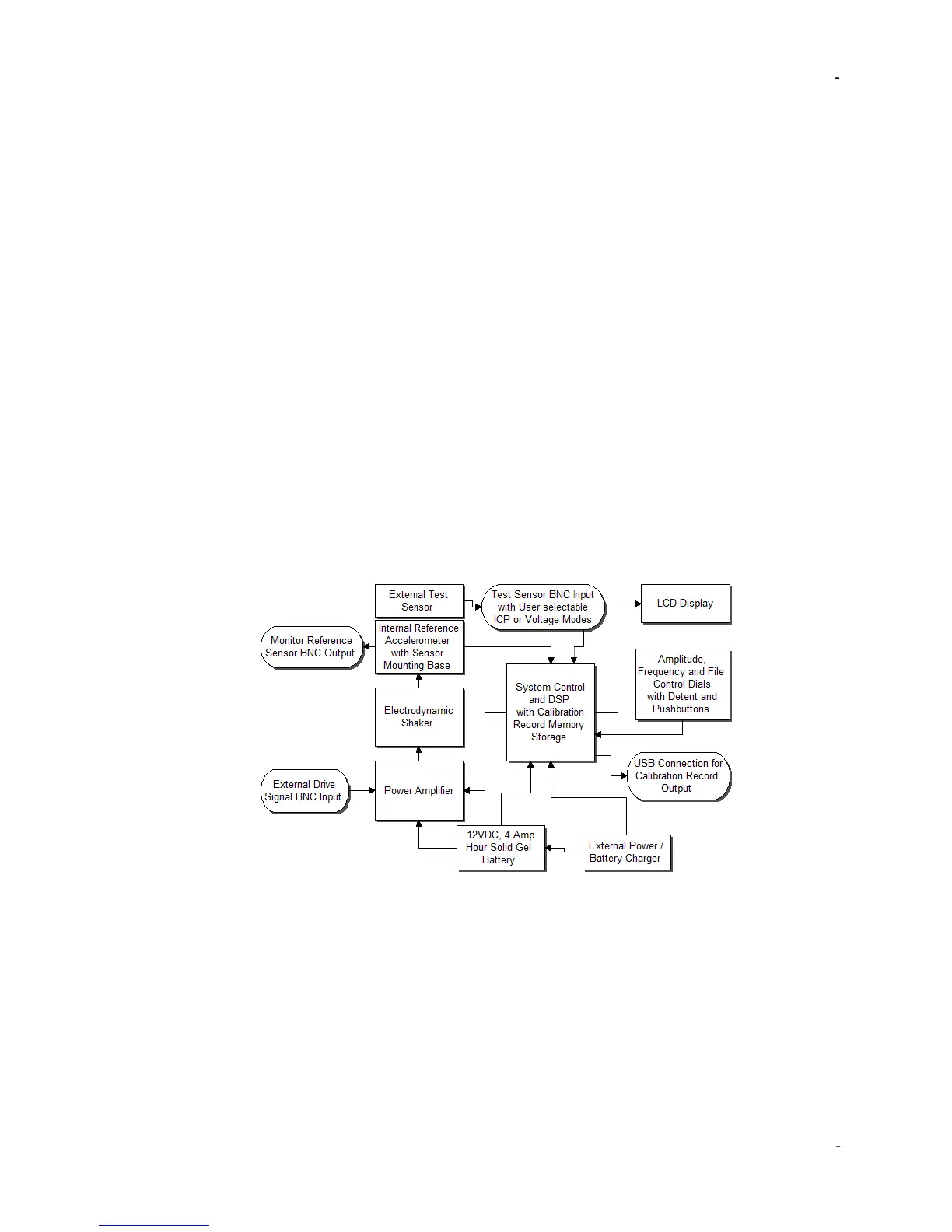
Theory of Operation
Instrumentation
The Model 699A07 Portable Vibration Calibrator internal electrical system is
comprised of several different mechanisms:
• Electrodynamic Shaker
• Power Amplifier
• Reference Accelerometer
• Signal Generation Electronics
• Sensor Signal Measurement Electronics
• LCD Digital Display
• 3 Dials with Detent and Integrated Pushbuttons
• 12 VDC, 4 Amp Hr Solid Gel Battery
• External Charger
• Three different BNC ports: “External Source In,” “Monitor Reference Out”
and “Test Sensor In”
• USB Flash Drive Port
The LCD display continuously shows the frequency of the shaker drive signal and
the vibration amplitude of the mounting platform as measured by the reference
accelerometer.
The reference accelerometer is a PCB Piezotronics ICP® quartz shear sensor,
integrated into the mounting platform. A calibration “standard” maintained by IMI is
used to calibrate the 699A07 as a complete system and provides NIST traceability.
Traceability information can be viewed under the tools menu as described in the
previous section.
The power amplifier is specifically designed to provide the current required to drive
the electrodynamic shaker. The electronic signal processing system produces a
variable frequency sine wave to the power amplifier, which becomes the source of
the driving signal to produce the vibration at the mounting platform.
 Loading...