IMI Sensors: A PCB Piezotronics Div 699A07 User Manual
MAN-0192 rev A Page 38 of 39 800-959-4464
4. Set the amplitude to the first vibration alert or just greater than first alert, call the
control room to confirm alert.
5. Set the amplitude to the second (severe) vibration alarm or just greater, call the
control room to confirm alarm.
6. Confirm with control room displayed vibration matches that shown on the 699A07.
7. Continue testing at any additional vibration alarm points.
Creating a test report for 4-20 mA vibration transmitters
For safety or insurance audits it may be helpful to have test reports for 4-20 mA
vibration transmitters. The 699A07 cannot read DC voltage or current, thus for this
test a calibrated multi-meter (capable of measuring current) is required. Also a USB
to 24 VDC power supply can be optionally used to power the sensor using the
USB connection on the 699A07. Contact IMI for ordering information. The
following instructions include using a USB to 24 VDC power supply. If it will not
be used skip to step 5.
1. Mount the 4-20 mA vibration transmitter to the shaker table. Users may need a mounting
adaptor such as ¼” NPT available from IMI Sensors.
2. Make sure the 699A07 is turned off, connect the sensor’s leads to appropriate positions
on the terminal block: +24 VDC, SIG IN and GND (ground). For example, for an IMI
Sensors Model 640B01 and Model052BRXXXAD cable connect the RED wire to +24
VDC, the BLUE wire to SIG IN and the cable’s shield to GND.
3. Connect the DAQ BNC output to the calibrated multi-meter and set the meter to measure
DC current. A BNC jack to banana plug is the simplest method of connection. BNC jack
to banana plugs are commercially available from any electrical hardware store (IMI uses
Pomona model 1269 BNC jack to banana).
4. Plug the power supply unto the USB port on Model 699A07.
5. Turn on the shaker table.
6. Open the Report Generation Workbook on a computer and click the LINData tab.
7. Under the “Static Proximity Probe/4-20 mA Vibration Sensor Calibration Data Table” at
right, click cell H12 and choose appropriate scale (acceleration, velocity or
displacement). For aforementioned Model 640B01 “velocity” would be chosen.
8. In cell H13, select the appropriate sub-scale (for velocity: ips pk, ips RMS, mm/sec pk or
mm/sec RMS). For IMI Model 640B01 “ips pk” would be chosen.
9. In cell I13, choose “mA” as the output.
10. The starting point should be 0.0, record this in cell H14. Read the mA value on the multi-
meter and record in cell I14.
11. For first amplitude test point, read vibration value from display of 699A07, record in
column H then read mA value from multi-meter and record in column I. Repeat until test
is complete.
12. When all data has been entered press “view certificate” and print or save. Optionally
enter additional test data like model number, serial number, location and notes.
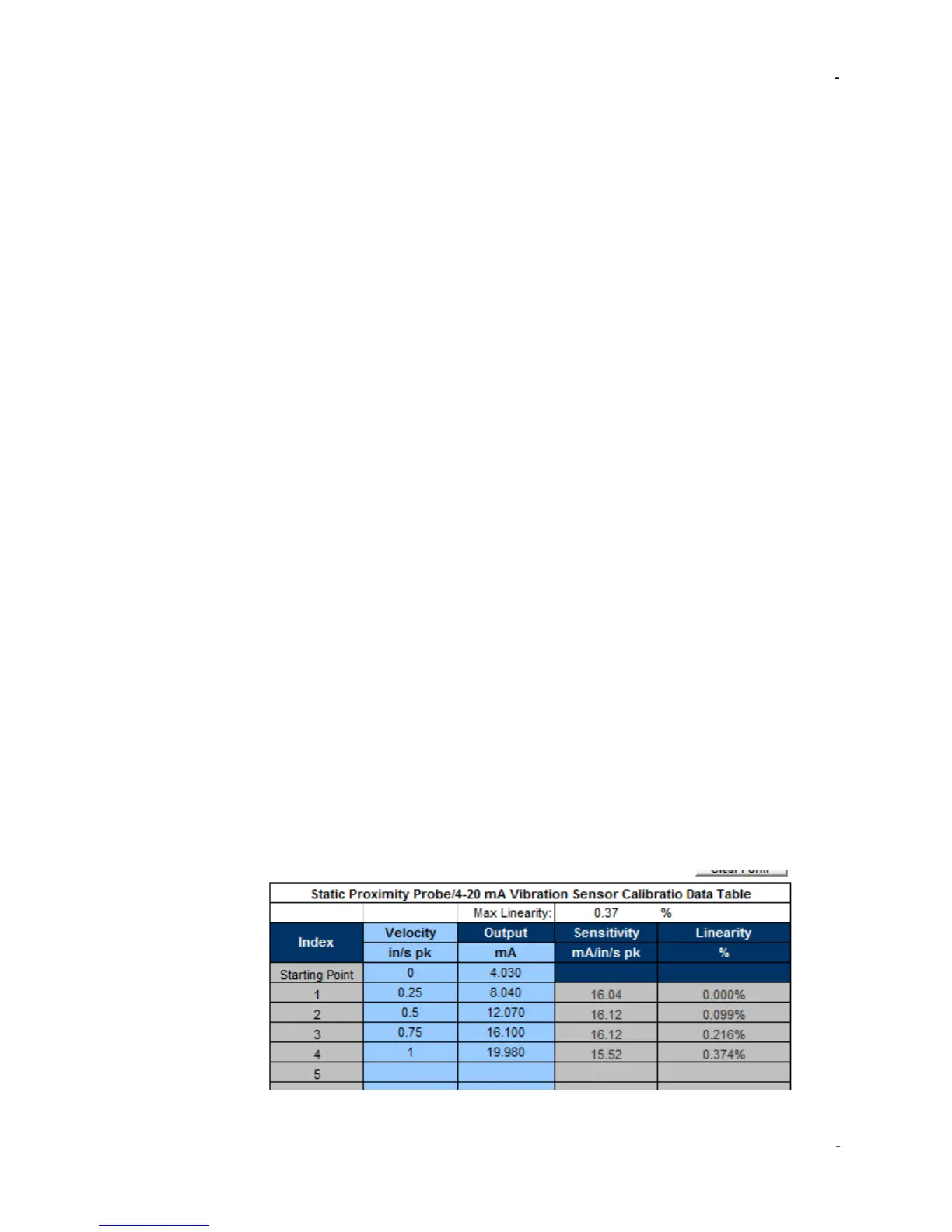
A good test is to take five test points (including zero), evenly spaced through the
range. Be sure to confirm operation at vibration alarm points. Example test data for
IMI Sensors Model 640B01:
 Loading...