IMI Sensors: A PCB Piezotronics Div 699A07 User Manual
MAN-0192 rev A Page 33 of 39 800-959-4464
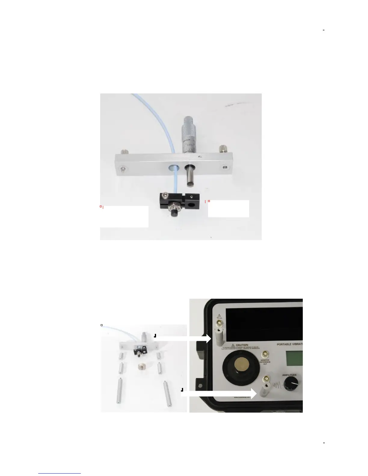
3. Install the non-contact displacement sensor in the microarm after stringing the
probe through the probe bar as shown in the picture below. Please note: An 8 mm
probe tip non-contact displacement sensor with 3/8-24 threaded case will mount
directly while a 5 probe tip mm non-contact displacement sensor with a ¼-28
threaded case requires the supplied bushing. Slide the non-contact displacement
sensor into the microarm. Tighten the socket head cap screw inside the microarm to
lightly squeeze the probe to ensure the probe is held securely.
4. Carefully lay out the assembly to resolve the required spacer or spacers to hold
the non-contact displacement sensor the proper distance from the target as shown
below. The non-contact displacement sensor will need to be held so that the sensor
will contact the target and must be capable of traveling 100 mils before the
micrometer runs out of travel. (for 200 mV/mil probe with 10-90 mils range). Non-
contact displacement sensors come in various lengths so adjustability has been
designed into the assembly. Attach selected spacer or spacers using setscrews
provided, leaving threaded holes exposed.
Set Screw
Socket Head
 Loading...