23
3-2
5
1
2
6
5
4
3
4
4
5
11
7
7
7
12
12
7
13
13
11
4
5
5
7
4
10
10
10
10
9
8
INSTALLERUSER
MAINTENANCE TECHNICIAN
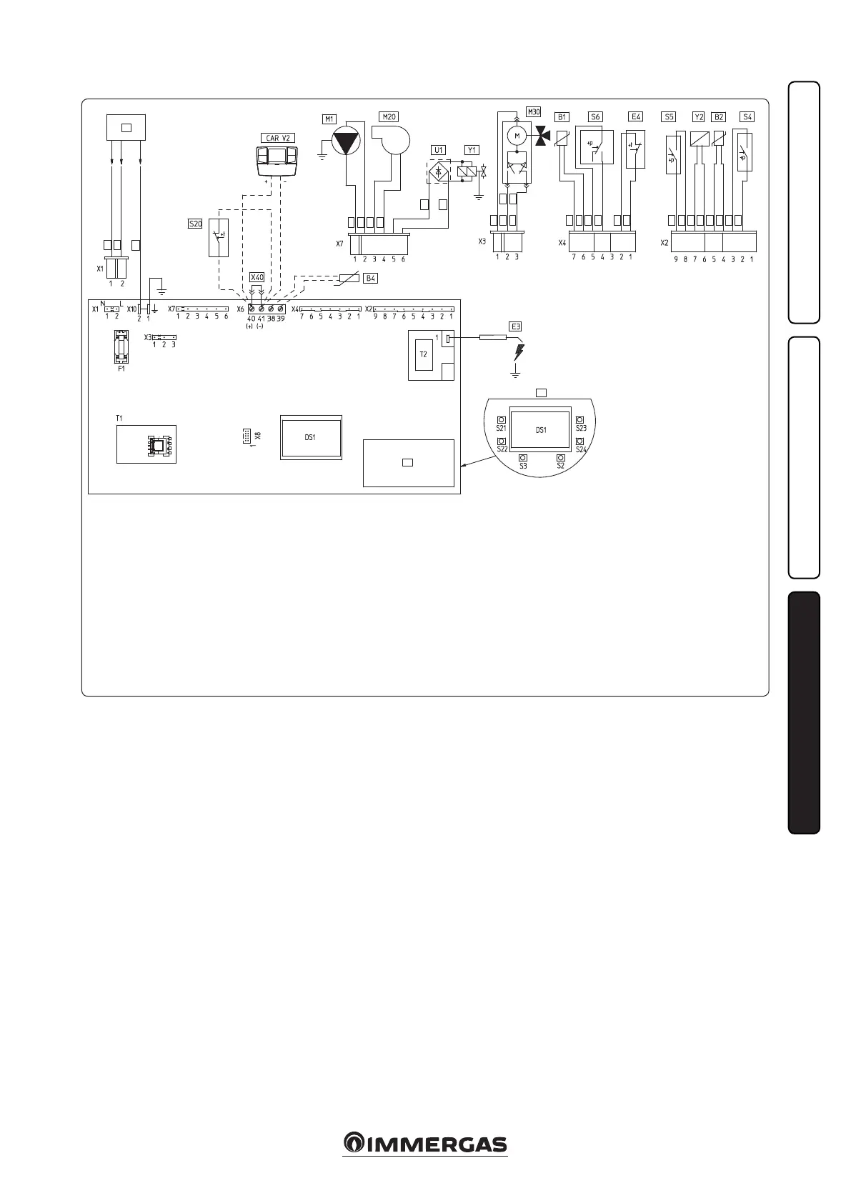
3.2 WIRING DIAGRAM.
Key:
B1 - Flow probe
B2 - Domestic hot water probe
B4 - External probe
CAR
V2
- Comando Amico Remoto
V2
remote control Version 2 (optional)
DS1 - Display
E3 - Ignition and detection electrodes
E4 - Safety thermostat
F1 - Phase fuse
M1 - Boiler pump
M20 - Fan
M30 - ree-way valve
S2 - Selector switch functioning
S3 - Reset block keys
S4 - Domestic hot water ow switch
S5 - System pressure switch
S6 - Flue gas pressure switch
S20 - Room thermostat (optional)
S21 - Domestic hot water temperature
increase key
S22 - Domestic hot water temperature
reduce key
S23 - Heating temperature increase key
e boiler is designed for application of a room
thermostat (S20), an On/O room chronother-
mostat, a program timer or a Comando Amico
Remoto
V2
remote control (CAR
V2
). Connect
to clamps 40 - 41 eliminating the jumper X40,
paying attention not to invert the polarity if the
CAR
V2
is installed.
e connector X8 is used for the connection
of the Virgilio Palmtop in the microprocessor
soware updating operation.
3.3 TROUBLESHOOTING.
N.B.: Maintenance must be carried out by a
qualied technician (e.g. Immergas Technical
Aer-Sales Assistance Service).
- Smell of gas. Caused by leakage from gas circuit
pipelines. Check sealing eciency of gas intake
circuit.
- e fan works but ignition discharge does not
occur on the burner ramp. e fan may start
but the safety air pressure switch does not
switch the contact over. Make sure:
1) the intake/exhaust duct is not too long (over
allowed length).
2) the intake/exhaust duct is not partially
blocked (on the exhaust or intake side).
3) the diaphragm of the ue exhaust is adequate
for the length of the intake-exhaust duct.
4) that the sealed chamber is kept in good condi-
tions.
5) the fan power supply voltage is not less than
196 V.
- Irregular combustion (red or yellow ame).
is may be caused by: dirty burner, incorrect
combustion parameters, intake - exhaust ter-
minal not correctly installed. Clean the above
components and ensure correct installation of
the terminal.
- Frequent interventions of the over heating
safety thermostat. It can depend on reduced
water pressure in the boiler, little circulation
in the heating system, the blocked pump or
an anomaly of the boiler P.C.B. Check on the
manometer that the system pressure is within
established limits. Check that radiator valves
are not all closed.
- Presence of air in the system. Check opening of
the hood of the special air vent valve (Fig. 1-29).
Make sure the system pressure and expansion
vessel pre-charge values are within the set
limits; the pre-charge value for the expansion
vessel must be 1.0 bar, and system pressure
between 1 and 1.2 bar.
- Ignition block see par. 2.5 and 1.4 (electric
connection).
S24 - Heating temperature
reduce key
T1 - Low voltage feeder
T2 - Switch-on transformer
U1 - Rectier inside the gas valve
connector (Only available
on Honeywell gas valves)
X40 - Room thermostat jumper
Y1 - Gas valve
Y2 - Gas valve modulator
1 - User interface
2 - N.B.: e user interface is on
the welding side of the boiler
board
3 - 230 Vac 50Hz power supply
4 - Blue
5 - Brown
6 - Yellow/Green
7 - Black
8 - (DHW)
9 - (central heating)
10 - Grey
11 - White
12 - Red
13 - Green