29
INSTALLERUSER
MAINTENANCE TECHNICIAN
3.17 YEARLY APPLIANCE CHECK AND
MAINTENANCE.
e following checks and maintenance should
be performed at least once a year.
- Clean the ue side of the heat exchanger.
- Clean the main burner.
- Visually check the ue hood for deterioration
or corrosion.
- Check correct lighting and functioning.
- Check correct calibration of the burner in
domestic hot water and central heating phases.
- Check correct functioning of control and
adjustment devices and in particular:
- the intervention of main electrical switch
positioned outside of the boiler;
- system control thermostat intervention;
- domestic hot water control thermostat inter-
vention.
- Check sealing eciency of the gas circuit and
the internal system.
- Check the intervention of the device against no
gas ionisation ame control. Intervention time
must be less than 10 seconds.
- Visually check for water leaks or oxidation
from/on connections.
- Visually check that the water safety valve drain
is not blocked.
- Check that, aer discharging system pressure
and bringing it to zero (read on boiler manom-
eter), the expansion vessel factory-set pressure
is at 1.0 bar.
- Check that the system static pressure (with
system cold and aer relling the system by
means of the lling valve) is between 1 and 1.2
bar.
- Visually check that the safety and control
devices have not been tampered with and/or
shorted, in particular:
- temperature safety thermostat;
- water pressure switch,
- air pressure switch
- Check the condition and integrity of the electri-
cal system and in particular:
- electrical power cables must be inside the
whipping;
- there must be no traces of blackening or
burning.
N.B.: on occasion of periodical maintenance of
the appliance it is appropriate also to check and
perform maintenance on the central heating
system, in compliance with that indicated by the
regulations in force.
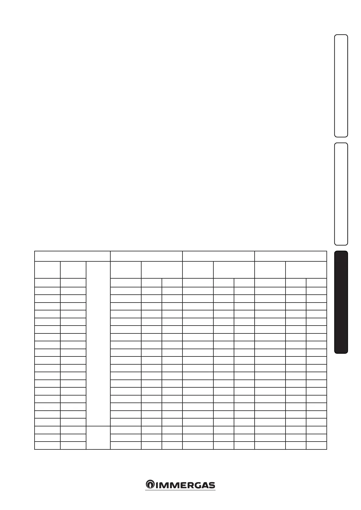
3.18 VARIABLE HEAT OUTPUT.
N.B.: the pressures indicated in the table repre-
sent the dierence in existing pressures between
the gas valve outlet and the combustion chamber.
e adjustments should therefore, be carried
out using a dierential manometer (small “U”-
shaped column or digital manometer) with the
probes inserted in the pressure test gas valve
outlet and on the sealed chamber positive pres-
sure test. e power data in the table has been
obtained with intake-exhaust pipe measuring 0.5
m in length. Gas ow rates refer to heating power
below a temperature of 15°C and at a pressure of
1013 mbar. Burner pressure values refer to use
of gas at 15°C.
METHANE (G20) BUTANE (G30) PROPANE (G31)
HEAT
OUTPUT
HEAT
OUTPUT
CH.
+
DH W.
BURNER GAS
FLOW RATE
PRESS. BURNER
NOZZLES
BURNER GAS
FLOW RATE
PRESS. BURNER
NOZZLES
BURNER GAS
FLOW RATE
PRESS. BURNER
NOZZLES
(kW) (kcal/h) (m
3
/h) (mbar) (mm H
2
O) (kg/h) (mbar) (mm H
2
O) (kg/h) (mbar) (mm H
2
O)
28.0 24080 3.14 11.50 117.3 2.35 28.00 285.5 2.31 36.00 367.1
27.0 23220 3.03 10.76 109.7 2.26 26.23 267.5 2.22 33.60 342.6
26.2 22516 2.94 10.17 103.7 2.19 24.84 253.3 2.16 31.71 323.4
25.0 21500 2.81 9.36 95.5 2.10 22.91 233.6 2.06 29.12 297.0
24.0 20640 2.70 8.71 88.8 2.02 21.34 217.6 1.98 27.04 275.7
23.0 19780 2.59 8.08 82.4 1.94 19.84 202.3 1.90 25.04 255.4
22.0 18920 2.49 7.48 76.3 1.86 18.39 187.5 1.83 23.14 236.0
21.0 18060 2.38 6.91 70.5 1.78 16.99 173.3 1.75 21.33 217.5
20.0 17200 2.27 6.36 64.8 1.70 15.65 159.6 1.67 19.59 199.8
19.0 16340 2.17 5.83 59.4 1.62 14.35 146.4 1.59 17.94 182.9
18.0 15480 2.06 5.32 54.3 1.54 13.11 133.6 1.52 16.36 166.8
17.0 14620 1.96 4.83 49.3 1.46 11.90 121.4 1.44 14.85 151.4
16.0 13760 1.85 4.37 44.5 1.38 10.74 109.5 1.36 13.41 136.8
15.0 12900 1.75 3.92 40.0 1.30 9.62 98.1 1.28 12.05 122.8
14.0 12040 1.64 3.49 35.6 1.23 8.54 87.1 1.21 10.75 109.6
13.0 11180 1.54 3.08 31.5 1.15 7.50 76.5 1.13 9.52 97.0
12.0 10320 1.43 2.69 27.5 1.07 6.50 66.3 1.05 8.35 85.2
11.2 9632 1.34 2.39 24.4 1.00 5.73 58.4 0.98 7.47 76.1
10.0 8600
D.H.W.
1.21 1.97 20.1 0.90 4.61 47.0 0.89 6.22 63.4
9.0 7740 1.10 1.63 16.6 0.82 3.72 37.9 0.81 5.25 53.6
8.5 7310 1.04 1.47 15.0 0.78 3.29 33.5 0.77 4.80 48.9