14
C82 C42
C52
1-22
1-24
C82
1-23
4
6
5
1
3
2
7
8
5
9
7
A
S
1-21
INSTALLERUSER
MAINTENANCE TECHNICIAN
male section (smooth) in the female section of
the bend (5) up to the stop, ensuring that the
internal and external wall sealing plates are t-
ted. Fit the exhaust pipe (9) with the male end
(smooth) to the female end of the bend (5) up
to the stop; making sure that the internal wall
sealing plate has been tted. is will ensure
sealing and joining of the elements making up
the kit.
• Coupling of extension pipes and elbows. To
install push-tting extensions with other ele-
ments of the ue extraction elements assembly,
proceed as follows: engage the pipe or elbow
with the male side (smooth) in the female
section (with lip seal) up to the stop on the
previously installed element. is will ensure
sealing eciency of the coupling.
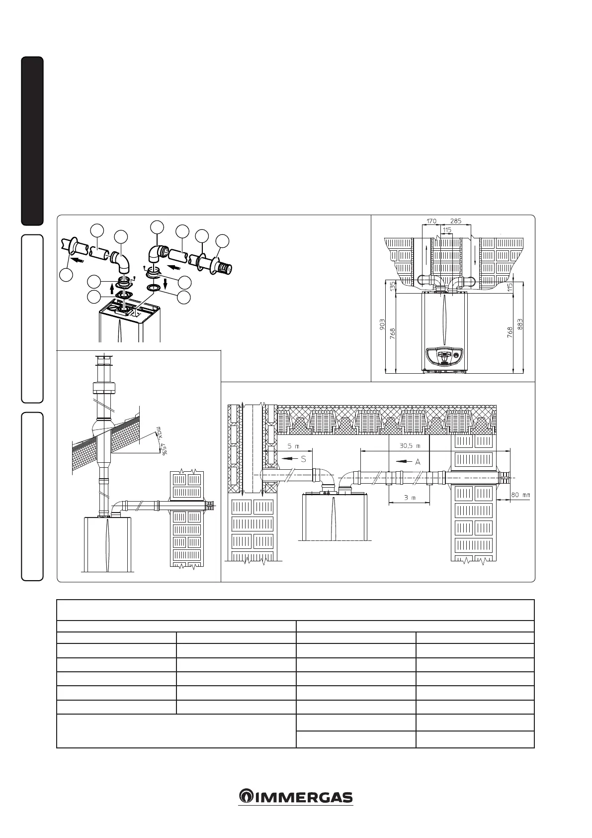
• Installation clearances. Figure 1-22 gives the
min. installation space dimensions of the
Ø80/80 separator terminal kit in limited condi-
tions.
• Figure 1-23 shows the conguration with verti-
cal exhaust and horizontal intake.
• Extensions for the separator kit Ø 80/80. e
max. vertical straight length (without bends)
that can be used for Ø 80 intake and exhaust
pipes is 41 metres of which 40 intake and 1
exhaust. The total length corresponds to a
resistance factor of 100. e total usable length
obtained by adding the length of the intake and
exhaust pipes Ø 80, must not exceed the values
stated in the following table. If mixed accessories
or components are used (e.g. changing from a
separator Ø 80/80 to a concentric pipe), the
maximum extension can be calculated by using
a resistance factor for each component or the
equivalent length. e sum of these resistance
factors must not exceed 100.
• Temperature loss in flue ducts. To prevent
problems of fume condensate in the exhaust
pipe Ø 80, due to fume cooling through the
wall, the length of the pipe must be limited to
just 5 m. (Fig. 1-24). If longer distances must
e kit includes:
N°1 - Exhaust gasket (1)
N°1 - Female intake ange (3)
N°1 - Flange seal (2)
N°1 - Female exhaust ange (4)
N°2 - 90° bend Ø 80 (5)
N°1 - Intake terminal Ø 80 (6)
N°2 - Internal wall sealing plates (7)
N°1 - External wall sealing plate (8)
N°1 - Exhaust pipe Ø 80 (9)
Maximum usable length
(including intake terminal with grill and two 90° bends)
NON-INSULATED PIPE INSULATED PIPE
Drain (metres) Intake (metres) Drain (metres) Intake (metres)
1 36.0* 6 29.5*
2 34.5* 7 28.0*
3 33.0* 8 26.5*
4 32.0* 9 25.5*
5 30.5* 10 24.0*
* e air intake pipe can be increased to 2.5 metres if the exhaust bend
is eliminated, 2 metres if the air intake bend is eliminated, 4.5 metres
eliminating both bends.
11 22.5*
12 21.5*
Important: if installation requires extending the ue ttings up to the exhaust a length that exceeds the 12 m recommended, it is necessary to properly
consider the possibility that condensation may form inside the duct and therefore Immergas “Serie Blu” insulated ue ttings, or other ue ttings with
similar characteristics, should be used.