9
1-6
1-7
INSTALLERUSER
MAINTENANCE TECHNICIAN
1.7 IMMERGAS FLUE SYSTEMS.
Immergas supplies various solutions separately
from the boiler regarding the installation of air
intake terminals and ue extraction, which are
fundamental for boiler operation.
Important: e boiler must only be installed
together with an original Immergas air intake
and ue gas exhaust system. is system can be
identied by an identication mark and special
distinctive marking bearing the note: “not for
condensing boilers”.
e ue exhaust pipes must not be in contact with
or be near to ammable materials. Moreover,
they must not pass through buildings or walls
made of ammable material.
See following paragraphs for the detailed descrip-
tion of the kits available
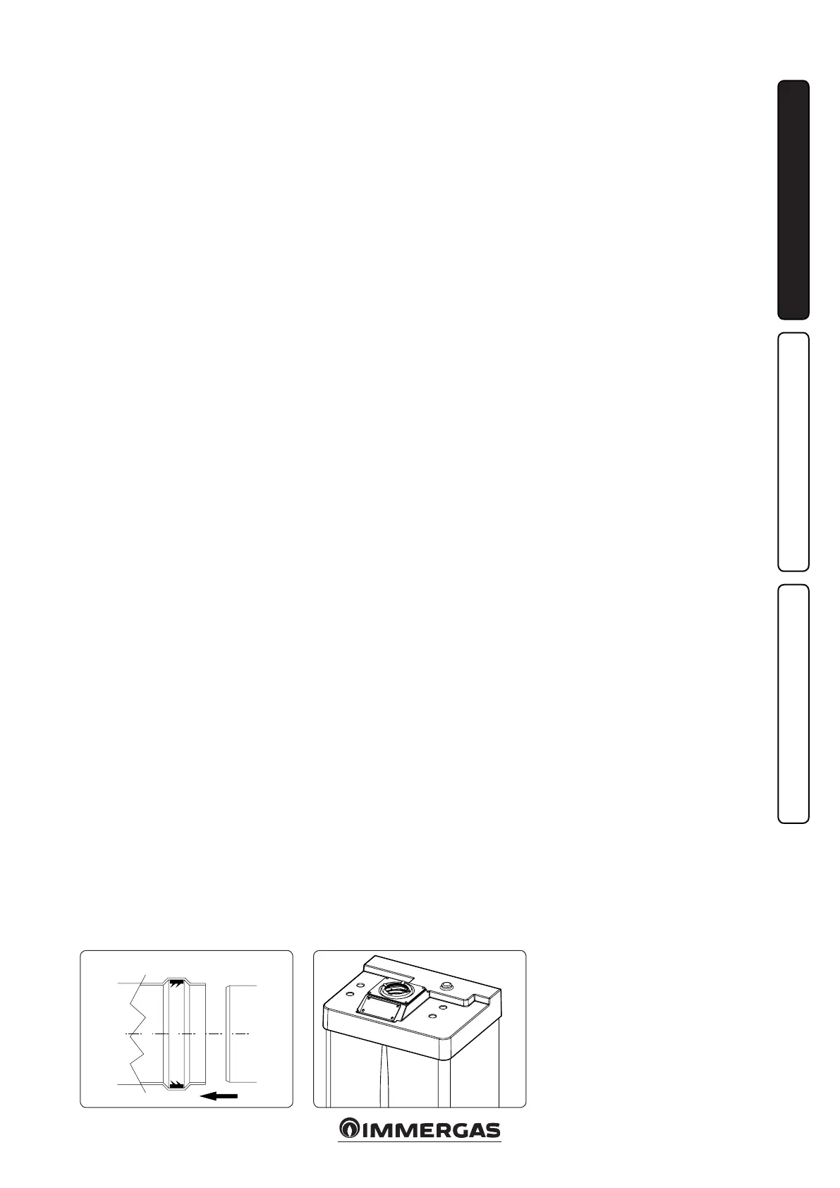
Positioning of double lip seals. For correct
positioning of lip seals on elbows and exten-
sions, follow the direction of assembly given in
gure (Fig. 1-6).
• Resistance factors and equivalent lengths. Each
ue extraction system component has a Resist-
ance Factor based on experimental tests and
specied in the table below. e resistance fac-
tor for individual components is independent
from the type of boiler on which it is installed
or the actual dimensions. It is, however, condi-
tioned by the temperature of the uids that pass
through the pipe and therefore varies according
to applications for air intake or ue exhaust.
Each single component has a resistance cor-
responding to a certain length in metres of pipe
of the same diameter; the so-called equivalent
length, obtained from the ration between the
relative Resistance Factors. All boilers have an
experimentally obtainable maximum Resistance
Factor equal to 100. e maximum Resistance
Factor allowed corresponds to the resistance
encountered with the maximum allowed pipe
length for each type of Terminal Kit. This
information enables calculations to be made
in order to verify the possibility of various
congurations of ue extraction systems.
1.8 OUTDOOR INSTALLATION IN
PARTIALLY PROTECTED AREA.
N.B.: a partially protected area is one in which the
appliance is not exposed to the direct action of the
weather (rain, snow, hail, etc..)..
• Conguration type B, open chamber and fan
assisted.
The relevant terminal must be used for this
conguration (present in the intake kit for the
installation in question), which must be placed
on the central hole of the boiler (Fig. 1-8). Air
intake takes place directly from the environment
in which the boiler is installed and ue exhaust
in individual ue or to the outside.
In this conguration the boiler is classied as
type B
22
.
With this conguration:
- air intake takes place directly from the environ-
ment in which the boiler is installed and only
functions in permanently ventilated rooms;
- the ue exhaust must be connected to its own
individual ue or channelled directly into the
external atmosphere.
The technical regulations in force must be
respected.
• Fitting the cover kit. To assemble and con-
gure the cover kit correctly, please refer to the
relative instructions sheet.
Max. length of exhaust duct. The flue pipe
(vertical or horizontal) can be extended to a
max. length of 12 m straight route, using insulated
pipes (Fig. 1-27). To prevent problems of fume
condensate in the exhaust pipe Ø 80, due to fume
cooling through the wall, the length of the pipe
(not insulated) must be limited to just 5 m.
Example of installation with direct vertical
terminal in partially protected location. When
the vertical terminal for direct discharge of com-
bustion fumes is used, a minimum gap of 300
mm must be le between the terminal and the
balcony above. e height X+Y+Z+W evaluated
with respect to the balcony above, must be equal
to or more than 2000 mm. (Fig. 1-9). e term W
must only be considered if the balcony above has
closed balustrade (W=0 if the balustrade is open).
• Configuration without cover kit (boiler
typeC).
By leaving the side plugs tted, it is possible
to install the appliance externally, in partially
covered places, without the cover kit. Installa-
tion takes place using the Ø60/100 and Ø80/125
concentric horizontal intake/ exhaust kits. Refer
to the paragraph relative to indoor installation.
In this conguration the top cover kit guarantees
additional protection for the boiler. It is recom-
mended but not compulsory.
Diaphragm installation. For correct functioning
of the boiler it is necessary to install a diaphragm
on the outlet of the sealed chamber and before the
intake and exhaust pipe (Fig. 1-10). e choice
of suitable diaphragm takes place on the basis
of the type of pipe and its maximum extension:
this calculation can be carried out using the
following tables:
N.B.: the diaphragms are supplied together with
the boiler.
Intake diaphragm installation. For correct
boiler functioning with Ø 80 separator kits and
drain measuring > 1 m a diaphragm Ø 47 must
be installed on the sealed chamber intake hole
and before the intake pipe (Fig. 1-11). e choice
of suitable diaphragm takes place on the basis
of the type of pipe and its maximum extension:
this calculation can be carried out using the
following tables: