10
5 Electrical Installation
WARNING
ELECTRICAL SHOCK HAZARD
Do not touch any electrical parts of the
inverter when the power supply is connect-
ed, even if the inverter output is at STOP.
After the power supply has been discon-
nected, the built-in smoothing capacitor
will hold a residual charge. It takes up to
10 minutes for the capacitor to discharge
completely. To avoid danger, wait until the
charge indicator LED is extinguished.
WARNING — SAFETY EARTHING
The inverter chassis, motor base and
equipment enclosure structure should be
earthed in accordance with the national
and local safety specifications in force.
CAUTION
Do not connect any supply voltage that
exceeds the standard voltages and varia-
tions specified on page 3, or the inverter
will be damaged and the Warranty will be
invalidated.
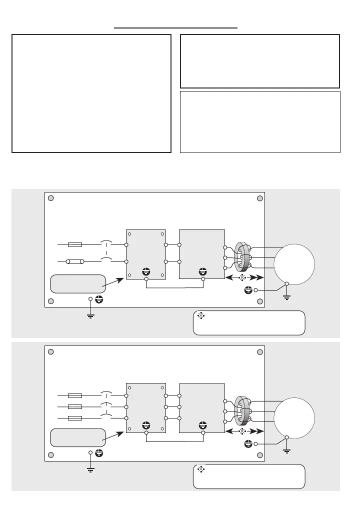
5.1 Power Connection Block Diagrams
These diagrams are not suitable for Electromagnetic Compatibility (EMC), refer to page 58.
For the Table of Cable Sizes and Maximum Lengths, refer to page 63.
L
N
Jaguar
VXS
Inverter
Input
contactor
U
V
W
E
RF
FILTER
(Footprint
type FP)
HRC
Fuse
or MCB
FERRITE
RING
(Two
turns)
Keep distance (and conductors)
between inverter and motor
cable entry as short as possible.
Steel or aluminium Back Plate
Line
Load
M
L
N
Link
F
LK
E
Remove paint at
fixing points
Jaguar
VXS
Inverter
Input
contactor
U
V
W
E
RF
FILTER
(Footprint
type FP)
HRC
Fuse
or MCB
FERRITE
RING
(Two
turns)
Keep distance (and conductors)
between inverter and motor
cable entry as short as possible.
Steel or aluminium Back Plate
Line
Load
M
L1
Link
E
Remove paint at
fixing points
L2
L3
L1
L2
L3
240V 50/60Hz Single-phase
415V 50/60Hz Three-phase