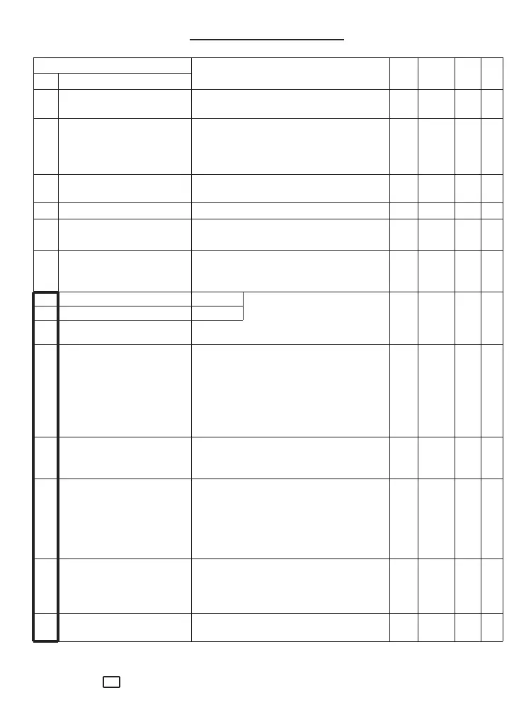
Functions in can be adjusted while the inverter is running. Data in […] applies to three phase inverters.
Resol. = resolution; Def. = Factory-set defaults — refer to Function 39.
21
00 Data protection 0 = No protection — — 0
(See also Function 57) 1 = Data protected (read only)
01 Input frequency reference 0 = Keypad mode, ∧ and ∨ keys — — 0
— mode 1 = Terminal mode, 12/C1-11
2 = Motorised pot.
refer to diagrams, p.26
3 = Motorised pot.
02 Control mode 0 = Keypad mode, RUN, STOP — — 0
1 = Terminal mode, P24-FWD/REV
03 Max. output frequency 50 to 400 Hz 1 50
04 Base frequency 1 (Motor 1) 15 to 400 Hz 1 60
(for Base freq. 2 see F62)
05 Max. output voltage 0 = V ∝ f (V ≤ V
L
max.) V 1 230
0, 80 to 240 [0, 160 to 480] [2] [400]
— selectable V ‘shelving’
06 Acceleration time 1 0 to 3600 0.00 to 9.99 s 0.01 6.00
07 Deceleration time 1 0 to 3600 10.0 to 99.9 s 0.1 6.00
100 to 999 1
(for Acc,/Dec. 2 see F63/64) 1000 to 3600 10
08 Torque boost 1 0 = Automatic torque boost — 1 0
1 = Squared characteristic (for pumps
and fans)
2 = Proportional characteristic
3 = Low linear boost…
…increasing in unit steps to…
(for Torque boost 2 see F65) 31 = High linear boost
09 FMA voltage 0 = 6.5V approx. — 1 85
…increasing in units steps to…
99 = 10.5V approx.
10 Motor poles 2 = 2-pole — 2 4
…increasing in steps of 2 to…
12 = 12-pole
Example: When a 4-pole motor is
running at 50Hz, display will read:
120 x 50 ÷ 4 = 1500rpm
11 Line speed coefficient 0 to 200 0.01 to 9.99 — 0.01 0.01
10.0 to 200.0 0.1
Example: Display value in m/min =
O/P freq. (Hz) x coefficient
12 PWM carrier frequency 0 = 0.75kHz kHz 1 5
1 = 1kHz, to 15 = 15.6kHz
7 Inverter Functions
7.1 Functions Data
Function
Setting Range Unit Resol. Def.
No. Name