26
When Function 00 = 1, all data becomes
‘read-only’. To change Function 00, simulta-
neously press the STOP key and either ∧ or ∨.
Refer also to Function 57 — special use of
terminal THR to protect Function data.
Jaguar VXS inverters can be controlled entirely
at the keypad, or by inputs to control terminals
only, or by a combination of keypad inputs and
terminal inputs. (Refer to Function 02.)
As delivered from the factory, Function 01 = 0.
It cannot be changed while the link at terminals
FWD-P24 is in place. If the link has been
removed and replaced by an external FWD
and/or REV control circuit, the contacts must be
of the normally-open type.
When Function 01 = 0, the frequency refer-
ence input is provided at the keypad, using the
∧ and ∨ keys.
When Function 01 = 1, the ∧ and ∨ keys are
disabled and the frequency input reference is
provided by voltage and/or current input refer-
ence signals at terminals 12 and C1. (Refer to
pages 14 and 15).
NOTE If both a voltage and a current input
reference signal are applied, the input
reference is the sum of the two.
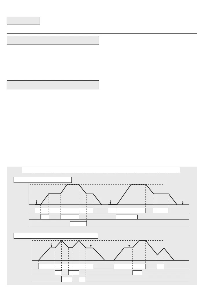
Motorised pot. mode
When Function 01 = 2 or 3, the inverter
responds to commands at terminals
FWD/REV-P24, X1-P24 and X2-P24 as
shown in the example diagrams below. When
FWD/REV-P24 is OFF (STOP command), the
next initial frequency is either zero (F01 = 2)
or is the last previous frequency (F01 = 3).
Accel/decel 2 can be applied by X4-P24.
Refer to Function 43.
NOTE Output frequency may be further
modified by Functions 34 and 35.
7.2 Descriptions of Functions
00 Data protection
Title boxes with a heavy type and border indicate Functions which can be adjust-
ed while the inverter is in RUN mode. Otherwise, the inverter must be in STOP
mode. Data shown in […] applies to 3-phase inverters.
XX Function
01 Input frequency reference
Output
Hz
t
ON
X2-P24
Max. freq.
ON
FWD-P24
ON ON
X1-P24
0
ON
ON
ON
** *
Output
Hz
t
X2-P24
Max. freq.
ON
FWD-P24
X1-P24
0
ON
**
ON
ON
ON
ON
**
**
ON
RAMPS: Default is Accel./Decel. 1. Accel./Decel. 2 if F43 = 0 and X4-P24 is ON
* Initial value = 0
F01 = 2
** Initial value = Previous value
F01 = 3
ON