10.4 RF Ferrite Physical Data
62
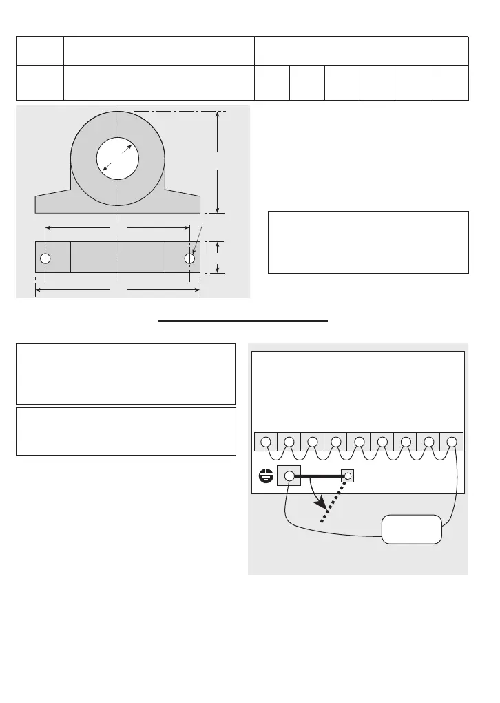
11.1 Insulation Testing
1 Disconnect the link at the earth terminal
— see NOTE 1 on the diagram.
2 Link together terminals as follows —
Single-phase inverters:
L, N, P1, (+), DB, U, V, W. (VXS20-1
inverters do not have a terminal DB.)
Three-phase inverters:
L1, L2, L3, P1, (+), DB, U, V, W.
3 Connect the insulation tester as shown.
Test voltage applied to the inverter must
not exceed 500V DC.
4 If the test is satisfactory, remove all tempo-
rary links installed in step 2.
5 Reconnect the link to the earth terminal
— see NOTE 1 on the diagram.
Continuity Testing of Control Circuits
Use a high-resistance tester, not a ‘megger’ or
a buzzer.
Connections for insulation testing.
L1 L2 L3 P1 (+) DB U V W
VXS
Inverters
1-phase & 3-phase
power terminals
[L] [N][—]
NOTE 1
“Megger”
500V DC
+
-
WARNING
SWITCH OFF AND ISOLATE the main
power supply to the inverter before mak-
ing any test connections.
CAUTION
Do not perform an insulation test on any
control circuit terminals.
11 Supplementary Data
W
d
H
Z dia.
X
D
Part Jaguar VXS Dimensions (mm)
number inverter range W H D X Z dia. d dia.
OC1 VXS20-1, 40-1, 75-1, 40-3, 75-3 85 46 22 70 5 21
OC2 VXS150-1, 220-1, 150-3, 220-3, 400-3 105 62 25 90 5 28.5
CAUTION
Do not overtighten the fixing screws
through the base flanges of the ferrite
(at ‘Z’)