15
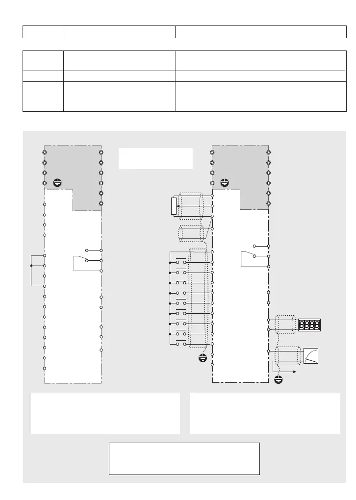
5.5 Control Circuits and Terminals
13
12
11
FWD
REV
THR
CM
X1
X2
X3
X4
BX
RST
P24
CMC
Y1E
30C
30B
30A
Trip
relay
Open collector O/P
P24
CM
FMP
FMA
Pulse O/P
0-10V analog O/P
Keypad Operation
Terminal Operation
Analog voltage
freq. ref. input
0V to 10V
(Pot. 1kΩ, 1W)
Programmable
digital
output
+
-
Analog current
freq. ref. input
(4-20mA)
Programmable
analog
output
to terminal 11
(+)
N/C
C1
DB
P1
V
W
U
[L2]
[L3]
[L1]
(+)
DB
P1
V
W
U
Trip
relay
NOTE 2
Open emitter O/P
Refer to Control
O/P Circuit, p.13
Blank
L
N
[L2]
[L3]
[L1]Blank
L
N
NOTE 1
13
12
11
FWD
REV
THR
CM
X1
X2
X3
X4
BX
RST
P24
CMC
Y1E
30C
30B
30A
P24
CM
FMA
FMP
C1
NOTE 1
Data in […] applies
to 3-phase inverters
CAUTION
Do not short-circuit terminal P24 to either 11
or CM. Damage may result.
NOTES
1 Terminal DB not available for VXS20-1.
2 Input to terminal THR, (N/C contact)
from external protection relay.
TRIP/ALARM RELAY
Relay is shown with the inverter in either the
power-off or power-on state, condition
‘healthy’.
5.4 Terminals Functions List continued
Terminal Terminal Function Description
Control Outputs
Y1E Open emitter output; 50mA max.
Six different functions are available according to
preset selection; refer to Function 54.
CMC Reserved for Y1E output only Refer to the illustration on page 13.
30A, 30B,
When no trip, N/O circuit 30A-30C; N/C circuit
30C
Alarm output, all trips 30B-30C. When inverter trips, 30A-30C closes.
Rating 48V DC, 0.3A.