For Motor 2 only. Refer also to Function 15.
There are five modes of the Function 66:
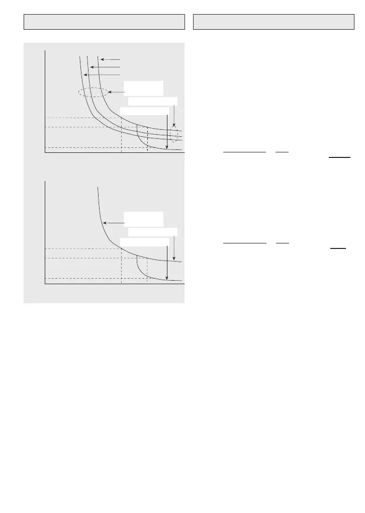
0 Inactive.
1 or 3 Active. The factory-set default — suit-
able for ‘standard’ 4-pole induction
motors.
2 or 4 Active. For inverter-rated motors.
Characteristic curves for the settings of
Function 66 = 1, 2, 3, 4 are shown above.
NOTE When Function 43 = 2, activating termi-
nal X4-P24 selects Thermal overload 2 and
also Functions 62, 63, 64, 65 and 67 auto-
matically.
For Motor 2 only. Refer also to Function 16.
Factory-set default level is at 105% of the cur-
rent rating of a standard 4-pole induction motor
appropriate to the capacity of the inverter. If it
is intended to use the inverter to drive a motor
of a different frame size, refer to Function 70.
Example 1: For a VXS400-3 4kW inverter
driving a 4-pole 2.2kW motor at 415V:
Inverter FLC = 9A
Typical 2.2kW motor FLC = 4.8A
Setting for Function 67 = 4.8
Check:
Motor FLC
=
4.8
= 0.533 or 53.3%
Inverter FLC 9.0
which is within the range of 20-105% of
inverter FLC and the motor is protected.
Example 2: For a VXS400-3 4kW inverter
driving a 4-pole 0.37kW motor at 415V:
Inverter FLC = 9A
Typical 0.37kW motor FLC = 1.08A
Setting for Function 67 = 1.08
Check:
Motor FLC
=
1.08
= 0.12 or 12%
Inverter FLC 9.0
This is outside the 20-105% range and the
motor is not protected by the inverter. A
stand-alone thermal protection relay should be
wired to the motor thermistor. Then set
Function 66 = 0 to disable Function 67.
NOTE When Function 43 = 2, activating termi-
nal X4-P24 selects Thermal overload 2 and
also Functions 62, 63, 64, 65 and 66 auto-
matically.
39
66 Thermal overload 2 — mode 67 Thermal overload 2 — level
Oper.
time
(sec)
50
≥50Hz
0 100 150 200
20Hz
0.5Hz
Function 66
= 1 or 3
Function 66 = 1
Function 66 = 3
1
150
300
Oper.
time
(sec)
500 100 150 200
Function 66
= 2 or 4
Function 66 = 2
Function 66 = 4
1
150
300
Function 66 = 1 or 3
Function 66 = 2 or 4
%
%
% set current (A)
% set current (A)
 Loading...